As wireless communication and RF electronics continue to evolve, high frequency PCB performance becomes critical. Applications such as 5G networks, radar systems, satellite communication, and RF front-end modules demand PCB materials that deliver ultra-low loss, stable dielectric properties, and controlled impedance for predictable high frequency signal performance.
RO3003 PCB is a premium Rogers PCB material widely used in high-frequency and microwave circuits. Its unique combination of low dissipation factor (Df), stable dielectric constant (Dk), and PTFE-based ceramic-filled structure makes it ideal for high frequency PCB, RF PCB, and microwave PCB applications.
What Is RO3003 PCB?
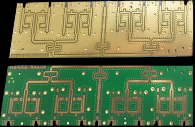
An RO3003 PCB is a high frequency printed circuit board manufactured using Rogers RO3003 laminate, designed specifically for RF, microwave, and high frequency signal PCB applications. Compared with standard FR-4, RO3003 offers:
-
Ultra-low dielectric loss for minimal signal attenuation
-
Stable Dk for reliable controlled impedance routing
-
High thermal reliability for stable performance in varying environments
-
Excellent performance for GHz-level signal transmission
RO3003 PCB is commonly used for RF front-end circuits, antenna feed networks, microwave filters, high-frequency transmission lines, and other demanding RF applications.
Key Advantages of RO3003 PCB
1. Ultra-Low Loss for High Frequency Signals
High frequency signal attenuation is a major concern for RF and microwave designs. RO3003 PCB minimizes insertion loss and maintains strong signal integrity even at GHz-level frequencies. Benefits include:
-
Improved RF efficiency and link performance
-
Reduced signal attenuation over long trace routing
-
Stable performance for high frequency and microwave circuits
2. Stable Dielectric Constant (Dk) for Controlled Impedance
Controlled impedance is crucial in RF PCB design. Variations in dielectric properties can lead to reflections, return loss, and degraded signal quality. RO3003 PCB provides:
-
Consistent microstrip and stripline impedance
-
Predictable phase and timing performance
-
Reliable RF signal transmission across production batches
This stability makes RO3003 ideal for precision RF designs such as filters, couplers, and antenna circuits.
3. High Frequency Signal Integrity
RO3003 PCB supports superior signal integrity in high frequency PCB and microwave designs. Its low dissipation factor and stable material properties reduce:
-
Insertion loss
-
Signal distortion
-
EMI and crosstalk
This ensures predictable and repeatable high frequency performance across multiple units.
Applications of RO3003 PCB
RO3003 PCB is widely used in industries that require high frequency and microwave performance:
-
5G communication modules and base stations
-
Radar systems and automotive radar
-
Satellite communication devices
-
RF front-end circuits, filters, and couplers
-
Antenna feed networks and matching circuits
-
Wireless communication modules and GPS devices
-
Aerospace and defense RF electronics
RO3003 PCB vs RO4003C PCB
While both are high frequency Rogers materials, RO3003 PCB is selected when:
-
Ultra-low loss is required at higher frequencies
-
Microwave performance is critical
-
Maximum signal integrity and stability are needed
RO4003C PCB is preferred when:
-
Cost-effectiveness is a priority
-
High frequency performance is needed but extreme low loss is not essential
-
Hybrid stack-ups with FR-4 are required
Design and Manufacturing Considerations for RO3003 PCB
To maximize performance, engineers should focus on:
-
Stack-Up Design – Control layer spacing for consistent impedance.
-
Trace Geometry – Accurate width and spacing for RF traces.
-
Via Transitions – Minimize via stubs and ensure high quality plating.
-
Ground Planes – Maintain continuous reference planes and add via stitching.
-
Surface Finish – Choose finishes that maintain low loss at high frequency.
-
Microstrip vs Stripline – Select based on EMI control and layout density.
Following these best practices ensures optimal signal integrity and reliable RO3003 PCB performance.
Conclusion
RO3003 PCB is an ideal high frequency and microwave PCB solution for applications requiring ultra-low loss, stable dielectric constant, and controlled impedance. Its superior material properties make it perfect for 5G, radar, satellite communication, and advanced RF front-end circuits.
For engineers seeking high frequency PCB solutions with predictable RF performance and reliable microwave performance, KKPCB offers professional RO3003 PCB manufacturing, stack-up design, and impedance-controlled fabrication services to ensure consistent and high-quality production.
