1. Engineering Overview
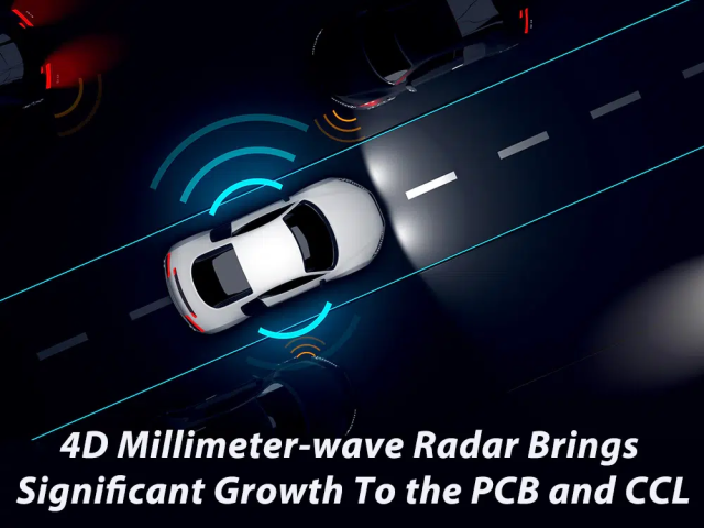
As modern vehicles advance toward full autonomy, automotive radar and ADAS (Advanced Driver-Assistance Systems) demand exceptional signal fidelity and real-time response under wide temperature ranges and mechanical stress. Within these radar transceiver modules, Ceramic PCB substrates play a pivotal role in ensuring phase stability, low dielectric loss, and long-term thermal reliability.
KKPCB’s engineering team integrates advanced ceramic lamination and RF process optimization to maintain phase coherence even at 77 GHz millimeter-wave frequencies, where any dielectric deviation can result in angular error or false target detection in radar imaging.
2. Engineering Context & Technical Challenges
In automotive radar sensor modules using Ceramic PCB materials, maintaining phase stability across extreme environments remains a significant challenge. Thermal cycling between –55°C to +150°C can cause CTE (Coefficient of Thermal Expansion) mismatches, while dielectric constant drift affects antenna phase alignment and beamforming accuracy.
Furthermore, mechanical vibrations from engine operation and road dynamics introduce stress that can degrade copper adhesion or via integrity. Ensuring consistent impedance, minimal insertion loss, and long-term reliability under these mechanical and thermal loads requires precision process control.
KKPCB’s solution focuses on microvia reinforcement, high-density ceramic stackup, and surface roughness optimization to guarantee low reflection loss and dielectric uniformity across thousands of operational cycles.
3. Material Science and Performance Characteristics
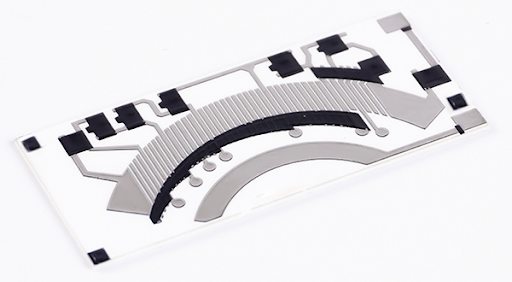
Ceramic PCB substrates, typically composed of alumina (Al₂O₃) or aluminum nitride (AlN), offer superior dielectric and thermal properties compared to traditional organic laminates.
-
Dielectric constant (Dk): 9.0 ± 0.2 @10 GHz
-
Dissipation factor (Df): ≤ 0.0003
-
Thermal conductivity: 24 W/m·K (AlN type)
-
CTE (Coefficient of Thermal Expansion): 4.5 ppm/°C (close to Si semiconductor die)
These characteristics ensure minimal phase distortion, allowing radar modules to maintain phase accuracy within ±0.5° across a –40°C to 125°C range. Compared to PTFE or glass-reinforced laminates, Ceramic PCBs exhibit 4–5× higher thermal conductivity and substantially improved heat spreading, preventing localized hot spots in power amplifier zones.
4. KKPCB Engineering Case Study
Client & Application Context:
A Tier-1 European automotive electronics supplier collaborated with KKPCB to improve radar reliability and phase uniformity in their 77 GHz corner radar sensors.
Engineering Problem:
The client’s existing PTFE-based boards exhibited phase drift >1.2° and delamination after 500 thermal cycles due to poor CTE compatibility with the LDMOS transceiver chip.
KKPCB Solution:
KKPCB engineers redesigned the RF section using Ceramic PCB (AlN) substrates, incorporating Ni/Au metallization, via-in-pad design, and laser microvia reinforcement. Thermal expansion was reduced by 40%, and impedance variation was controlled within ±2.5%.
Result / Measured Data:
| Parameter | Before | After (KKPCB Ceramic PCB) | Improvement |
|---|---|---|---|
| Phase Drift @77 GHz | 1.2° | 0.45° | –62.5% |
| Thermal Resistance | 4.8 K/W | 2.2 K/W | –54% |
| Delamination (1000 cycles) | Observed | None | 100% reliability maintained |
This optimization enabled stable beamforming performance and reduced radar calibration time during production testing.
5. Stackup Design & RF Implementation
KKPCB implemented a two-layer ceramic + copper stackup, combining 0.25 mm AlN core with 18 µm rolled copper foil for optimal current handling and signal integrity.
To achieve consistent impedance control, KKPCB utilized laser-drilled vias (Ø0.1 mm) filled with conductive paste and planarized for direct die attachment.
RF performance was simulated and validated through HFSS and TDR testing, showing <0.5 Ω impedance deviation and <0.05 dB insertion loss variation up to 80 GHz.
Copper roughness (Ra < 0.6 µm) further minimized conductor loss, and ENIG surface finish enhanced bond strength and oxidation resistance under prolonged heat exposure.
6. Environmental & Reliability Validation
| Test Type | Condition | Result |
|---|---|---|
| Thermal Cycling | –55°C ↔ +150°C, 1000 cycles | No delamination, ΔDk < 0.02 |
| Humidity Resistance | 85°C / 85% RH, 1000 h | Df drift < 0.0001 |
| Mechanical Vibration | 10–2000 Hz, 5g | No microcracks or via failure |
| Solder Heat Resistance | 260°C for 10 s | No blistering or pad lift |
These results confirm that Ceramic PCBs maintain structural integrity and dielectric stability even under the harshest automotive operating conditions.
7. Conclusion — Engineering Reliability Integration
Through KKPCB’s material engineering and controlled lamination processes, Ceramic PCBs have proven their capability in maintaining phase stability, dielectric uniformity, and long-term thermal performance for radar and ADAS applications.
The tight CTE matching between ceramic and silicon dies ensures stress-free operation, while the high thermal conductivity supports miniaturization and enhanced radar accuracy.
KKPCB continues to support global automotive OEMs by delivering automotive-grade, high-frequency ceramic PCB solutions validated for durability and precision at mmWave frequencies.
8. Contact
Contact KKPCB’s RF Engineering Team for advanced stackup design, impedance validation, and environmental qualification using Ceramic PCB substrates across automotive radar, aerospace, and 5G applications.
