
With the increasing adoption of industrial automation, robotics, intelligent equipment, and electric motion systems, motor drivers have become essential components for precise and efficient motion control.
A motor driver PCBA serves as the control and power interface between a controller and an electric motor. It manages:
- Motor speed regulation
- Torque control
- Direction control
- Current management
- Protection functions
Unlike simple motor control circuits, industrial motor driver PCBAs must handle complex requirements, including:
- High-current switching
- Real-time control signals
- Electromagnetic interference suppression
- Thermal management
- Long-term operational reliability
The performance of the PCBA directly affects motor efficiency, system stability, and equipment lifetime.
This case study presents how KKPCB supported the development of a customized motor driver PCBA solution, addressing challenges related to power design, signal integrity, thermal reliability, and manufacturing readiness.
1. Project Background
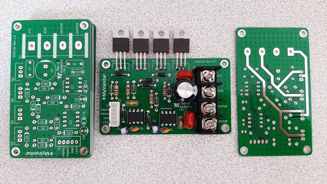
A customer developing an industrial motion control system required a customized motor driver module for integration into automated equipment.
The motor driver PCBA was designed to control electric motors used in:
- Industrial machinery
- Automated production equipment
- Motion control platforms
The system requirements included:
- Accurate motor control
- High efficiency
- Stable operation under continuous load
- Compact mechanical integration
- Reliable protection functions
The PCBA integrated multiple functional sections:
- Power conversion stage
- MOSFET/IGBT switching circuits
- Gate driver circuits
- MCU control unit
- Current sensing circuits
- Communication interfaces
During prototype validation, the customer identified challenges involving power stability, heat dissipation, and electromagnetic interference.
2. Key Challenges in Motor Driver PCBA Development
Challenge 1: High-Current Power Handling
Customer Pain Point
Motor driver modules must deliver high current to motors while maintaining electrical efficiency.
The PCB needed to withstand:
- High operating current
- Frequent switching cycles
- Dynamic load changes
Potential risks included:
- Excessive copper heating
- Voltage drop
- Power loss
- Component stress
The design required optimization of:
- Power trace width
- Copper thickness
- Current return paths
- Power plane structure
Challenge 2: Switching Noise and EMI Control
Customer Pain Point
Motor drivers use high-frequency switching devices such as:
- MOSFETs
- IGBTs
- SiC power devices
Rapid switching can generate:
- Voltage spikes
- Current ringing
- Electromagnetic radiation
These issues may affect:
- MCU operation
- Sensor signals
- Communication interfaces
The PCB required careful control of:
- Switching loops
- Grounding
- Signal isolation
Challenge 3: Motor Feedback Signal Integrity
Customer Pain Point
Accurate motor control depends on reliable feedback signals, including:
- Current sensing
- Encoder signals
- Position feedback
Noise interference may cause:
- Incorrect motor control
- Position deviation
- Reduced system accuracy
The PCB needed optimized routing for:
- Analog sensing signals
- Differential signals
- Control communication lines
Challenge 4: Thermal Management During Continuous Operation
Customer Pain Point
Motor drivers often operate under high loads for extended periods.
Major heat sources include:
- Power MOSFETs
- IGBT modules
- Driver ICs
- Current sensing components
Poor thermal management may lead to:
- Reduced efficiency
- Thermal shutdown
- Shortened component lifetime
The PCBA required improved:
- Heat dissipation paths
- Copper distribution
- Component placement
Challenge 5: Protection and System Reliability
Customer Pain Point
Industrial motor systems require protection against abnormal conditions.
The PCBA needed functions such as:
- Overcurrent protection
- Overvoltage protection
- Short-circuit protection
- Overtemperature protection
- Reverse polarity protection
Reliable protection helps prevent:
- Equipment damage
- Production downtime
- Safety risks
3. KKPCB Engineering Support and Solutions
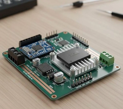
3.1 PCB Design Review and DFM Optimization
Before manufacturing, KKPCB engineering team conducted a comprehensive review covering:
- Circuit layout
- Power distribution
- Component placement
- Assembly feasibility
- Testing requirements
Optimization included:
- Improved component arrangement
- Enhanced power routing
- Added test points
- Reduced manufacturing risks
This supported a smoother transition from prototype development to production.
3.2 High-Current Layout Optimization
To improve motor driver performance, KKPCB optimized the power section.
Power Trace Enhancement
The engineering team evaluated:
- Current capacity requirements
- Copper thickness
- Trace geometry
The optimization improved:
- Current carrying capability
- Electrical efficiency
- Long-term reliability
Switching Loop Optimization
The design reduced:
- High-frequency loop area
- Parasitic inductance
- Switching interference
Benefits included:
- Lower voltage spikes
- Improved switching stability
- Reduced EMI generation
3.3 Gate Driver Circuit Optimization
For MOSFET/IGBT control circuits, KKPCB focused on:
- Short gate drive paths
- Proper driver grounding
- Improved isolation design
- Optimized power supply routing
These improvements helped achieve:
- Faster switching response
- Reduced switching losses
- Improved power device reliability
3.4 Signal Integrity Improvement
Sensitive control signals were optimized through:
- Separation from power switching areas
- Improved grounding strategy
- Shorter signal paths
- Noise filtering design
This enhanced:
- Current measurement accuracy
- Encoder signal reliability
- Control system stability
3.5 Thermal Design Improvement
The PCBA thermal structure was optimized through:
- Increased copper area
- Thermal via implementation
- Heat source distribution analysis
- Improved airflow consideration
The improvements supported:
- Lower operating temperature
- Higher reliability
- Longer service life
3.6 Protection Circuit Enhancement
The design integrated protection improvements including:
- Current monitoring circuits
- Voltage detection
- Temperature sensing
- Fault feedback mechanisms
These functions improved:
- System safety
- Fault response speed
- Equipment protection
3.7 Communication Interface Optimization
For intelligent motor control systems, PCB design supported interfaces such as:
- CAN
- RS-485
- Industrial Ethernet
Optimization included:
- Interface protection
- Noise filtering
- Signal integrity improvement
This ensured reliable communication between:
- Motor driver
- Main controller
- Industrial automation system
4. Manufacturing and Quality Control Process
PCB Fabrication
The motor driver PCB required strict manufacturing control.
Key considerations included:
- Multilayer PCB structure
- High-Tg FR-4 material
- Heavy copper capability
- Electrical isolation requirements
Manufacturing control included:
- Layer alignment
- Copper thickness verification
- Hole reliability inspection
SMT and THT Assembly
The motor driver PCBA combined:
SMT Components
Used for:
- MCU
- Driver ICs
- Sensors
- Control circuits
Through-Hole Components
Used for:
- Power connectors
- Large capacitors
- High-current terminals
Advantages:
- Strong mechanical reliability
- Improved current capability
Inspection and Testing
Quality verification included:
SPI Inspection
Checking:
- Solder paste printing accuracy
AOI Inspection
Detecting:
- Component placement issues
- Solder defects
X-Ray Inspection
Used for:
- Hidden solder joints
- Power connections
Functional Testing
Validation included:
- Motor speed control
- Current regulation
- Protection functions
- Communication stability
- Thermal performance
5. PCB Technologies for Motor Driver Applications
5.1 Heavy Copper PCB
Advantages:
- Higher current capacity
- Better thermal performance
Applications:
- High-power motor drivers
5.2 Multilayer PCB
Advantages:
- Improved power distribution
- Better signal isolation
- Higher circuit density
Applications:
- Industrial motion controllers
5.3 High-Tg PCB
Advantages:
- Better thermal stability
- Improved mechanical reliability
Applications:
- Continuous industrial operation
5.4 Metal Core PCB
Advantages:
- Enhanced heat dissipation
Applications:
- High-power drive systems
6. Applications of Motor Driver PCBAs
Industrial Robots
Applications:
- Robotic arms
- Collaborative robots
- Multi-axis motion systems
Automated Manufacturing Equipment
Applications:
- CNC machines
- Assembly equipment
- Precision motion platforms
AGV/AMR Systems
Applications:
- Autonomous vehicles
- Warehouse robots
Industrial Pumps and Fans
Applications:
- Motor control systems
- Energy-saving equipment
7. Project Results
Through PCB design optimization and manufacturing support, the motor driver PCBA achieved:
- Improved power stability
- Enhanced EMI performance
- Better thermal reliability
- Improved production consistency
Validation results included:
- 98%+ first-pass production yield
- Reduced debugging time during system integration
- Improved long-term operational reliability
8. Key Engineering Insights
8.1 Motor Driver Performance Depends on PCB Power Design
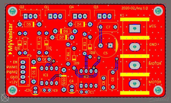
A reliable motor driver requires careful optimization of:
- Current paths
- Switching loops
- Thermal structures
- Protection circuits
PCB design directly influences:
- Efficiency
- Stability
- Service lifetime
8.2 Power and Control Circuits Must Be Properly Separated
Motor driver PCBAs combine:
- High-power switching circuits
- Sensitive control signals
Successful designs require:
- Grounding strategy
- Signal isolation
- EMI control
- Noise reduction
8.3 DFM Analysis Improves Production Reliability
Early engineering review helps identify:
- Assembly challenges
- Testing limitations
- Manufacturing risks
before mass production.
Conclusion
Motor driver PCBAs are critical components for modern industrial automation and motion control systems.
A reliable motor driver solution requires comprehensive optimization of:
- High-current power design
- Switching performance
- Signal integrity
- Thermal management
- Protection functions
- Manufacturing reliability
In this project, KKPCB supported the customer through PCB design optimization, power integrity improvement, EMI/EMC enhancement, thermal management design, and DFM analysis, helping transform a motor driver concept into a reliable and production-ready industrial control solution.
As automation systems continue moving toward higher efficiency, precision, and intelligence, customized motor driver PCBA solutions will remain essential for next-generation industrial equipment.
