Selecting the right PCB material is not just a design choice—it directly impacts signal integrity, thermal performance, manufacturability, and long-term reliability. For engineers and sourcing professionals, material selection often becomes the hidden factor behind project success or failure, especially in high-frequency, high-speed, or harsh-environment applications.
This guide breaks down how to choose PCB materials based on real engineering requirements, not generic theory.
1. Core Factors in PCB Material Selection
1.1 Electrical Performance (Dielectric Constant & Loss Tangent)
- Dielectric Constant (Dk): Affects impedance control and signal speed
- Loss Tangent (Df): Determines signal attenuation at high frequencies
Typical scenarios:
- High-speed digital (e.g., DDR, PCIe): Stable Dk required
- RF / microwave: Low Df is critical (e.g., <0.005)
If you’re working above 1 GHz, standard FR-4 is often not enough.
1.2 Thermal Performance
- Glass Transition Temperature (Tg): Stability under heat
- Thermal Conductivity: Heat dissipation capability
Typical ranges:
- Standard FR-4: Tg ~130–140°C
- High Tg FR-4: Tg ~170–180°C
- Metal-core / ceramic: much higher heat handling
For power electronics or LED boards, thermal management becomes a primary constraint, not a secondary one.
1.3 Mechanical Strength & Reliability
- Resistance to warpage
- Layer adhesion strength
- Stability under thermal cycling
Critical for:
- Automotive electronics
- Industrial control systems
- Aerospace applications
1.4 Cost vs Performance Trade-off
Material cost can vary 5–20x depending on type.
Over-specifying material is a common mistake in early-stage designs.
Use FR-4 unless performance forces you out of it.
2. Common PCB Material Types
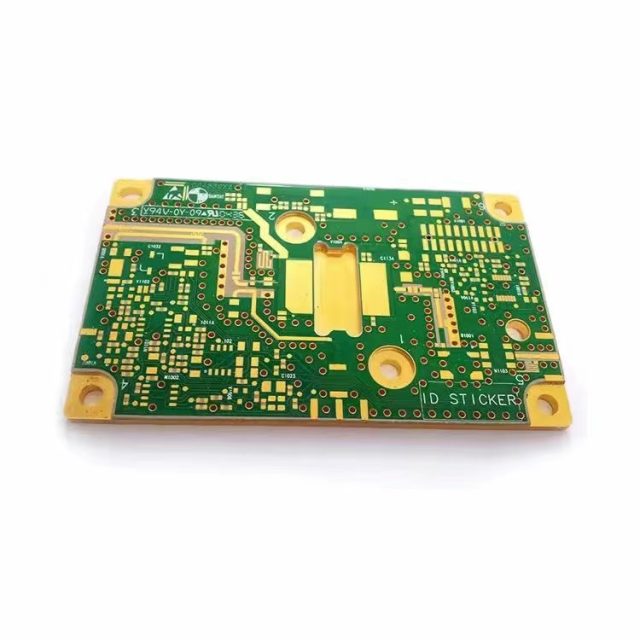
2.1 FR-4 (Standard & High Tg)
- Most widely used
- Good balance of cost and performance
- Suitable for general electronics
Limitations:
- Higher signal loss at high frequency
- Dk stability varies with frequency
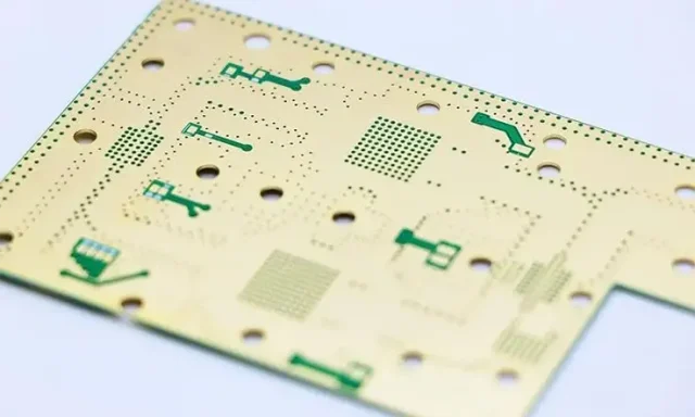
2.2 High-Frequency Materials
Typical examples:
- Rogers series
- PTFE-based laminates
Key features:
- Low Df (low signal loss)
- Stable Dk across frequencies
Applications:
- RF modules
- 5G antennas
- Radar systems
These materials require tighter processing control—manufacturing capability matters as much as material choice.
2.3 Metal Core PCB (MCPCB)
- Aluminum or copper base
- Excellent heat dissipation
Applications:
- LED lighting
- Power converters
- Automotive lighting
2.4 Ceramic PCB
- Extremely high thermal conductivity
- Excellent electrical insulation
Applications:
- High-power modules
- Aerospace
- Medical devices
High cost, used only when absolutely necessary.
3. Material Selection by Application
3.1 Consumer Electronics
- Material: Standard FR-4
- Focus: Cost efficiency + mass production
3.2 Automotive Electronics
- Material: High Tg FR-4 / specialized laminates
- Focus: Reliability + temperature resistance
3.3 RF & High-Speed Communication
- Material: Low-loss laminates (e.g., Rogers)
- Focus: Signal integrity
3.4 Power Electronics
- Material: Metal core / ceramic
- Focus: Thermal performance
4. Key Mistakes to Avoid
- Choosing material based only on price
- Ignoring loss tangent in RF design
- Over-specifying high-end materials unnecessarily
- Not aligning material with manufacturing capability
Material choice must match both design requirements AND supplier capability.
5. Practical Selection Workflow
- Define frequency / signal speed
- Evaluate thermal requirements
- Identify mechanical/environment constraints
- Match with available materials
- Verify with manufacturer stack-up capability
Conclusion
PCB material selection is a balance between performance, cost, and manufacturability. There is no “best” material—only the most suitable one for a specific application.
For most projects:
- Start with FR-4
- Upgrade only when electrical or thermal limits are exceeded
The earlier material decisions are aligned with real production conditions, the fewer redesigns and cost overruns you’ll face later.
