
What Is a Megtron 7 PCB?
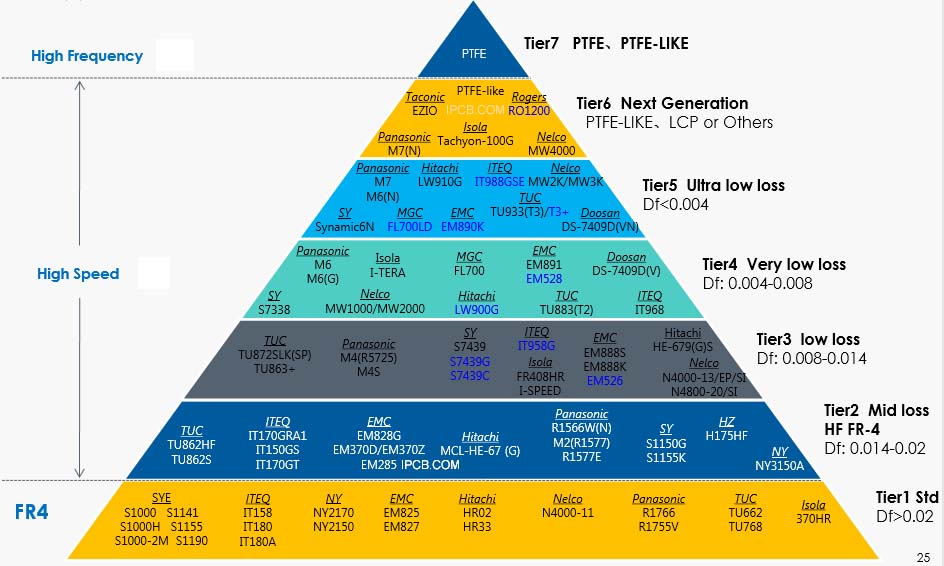
A Megtron 7 PCB is a high-performance printed circuit board built using Panasonic Megtron 7 laminate, developed for ultra-high-speed digital and high-frequency signal transmission.
Megtron 7 PCBs are widely used where signal integrity, extremely low transmission loss, and stable impedance control are critical, such as 5G routers, data-center equipment, ADAS systems, and high-speed test boards.
Key Material Properties of Megtron 7 PCB
Panasonic Megtron 7 laminate offers industry-leading electrical performance:
-
Dielectric constant (Dk): ~3.2
-
Ultra-low dissipation factor (Df): ~0.001
-
Excellent thermal reliability
-
Low moisture absorption
-
Superior dimensional stability
These properties make Megtron 7 PCB ideal for ultra-low loss PCB and high-speed PCB applications.
Advantages of Megtron 7 PCB
Using a Megtron 7 PCB provides significant technical advantages:
-
Extremely low insertion loss at high data rates
-
Outstanding signal integrity for high-speed interfaces
-
Stable impedance across wide frequency ranges
-
Excellent performance in multilayer designs
-
High reliability for long-term operation
Because of these advantages, Megtron 7 PCB is considered a premium solution for advanced systems.
PCB Design Considerations for Megtron 7 PCB
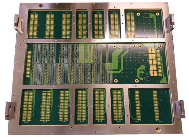
To fully utilize Megtron 7 PCB material, designers should focus on:
-
Precise impedance controlled PCB design
-
Stack-up optimization for high-speed signals
-
Minimized crosstalk and skew
-
Low-profile copper foil selection
-
Careful via and transition design
Close coordination between PCB design and manufacturing is essential for achieving ultra-low loss performance.
Manufacturing Requirements for Megtron 7 PCB
Manufacturing a high-quality Megtron 7 PCB requires advanced process control:
-
Tight dielectric thickness tolerance
-
High-precision multilayer alignment
-
Controlled copper surface roughness
-
Advanced lamination and drilling processes
-
Comprehensive impedance and electrical testing
Only experienced manufacturers can consistently deliver reliable Megtron 7 PCBs.
Applications of Megtron 7 PCB
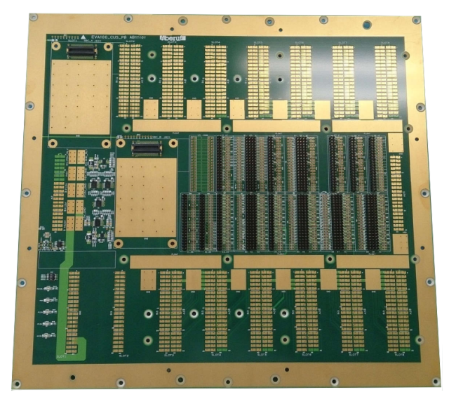
Megtron 7 PCBs are widely used in:
-
High-speed networking and switching equipment
-
5G routers and communication systems
-
Data-center and cloud infrastructure
-
ADAS and automotive electronics
-
High-speed test and measurement systems
-
Advanced computing and AI hardware
They are essential wherever high-speed and low-loss signal transmission is required.
Conclusion
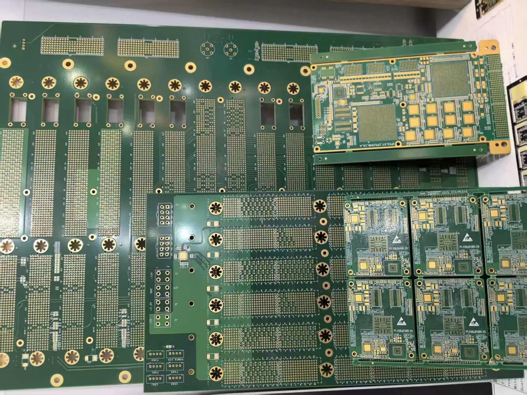
A Megtron 7 PCB delivers exceptional signal integrity, ultra-low loss, and long-term reliability for the most demanding high-speed and high-frequency applications. Its advanced material properties make it a preferred choice for next-generation electronic systems.
Choosing a professional Megtron 7 PCB manufacturer ensures accurate impedance control, consistent quality, and dependable performance from prototype to mass production.
There might be some differences in UL certification conditions between the existing part numbers and the new part numbers.
| MEGTRON 7 | New Part Number | Existing Part Number | ||
|---|---|---|---|---|
| Laminate | Prepreg | Laminate | Prepreg | |
| Low Dk Glass Cloth | R-578Y(N) | R-568Y(N) | R-5785(N) | R-5680(N) |
| Low Dk Glass Cloth Improved Processability |
R-578Y(GN) | R-568Y(GN) | R-5785(GN) | R-5680(GN) |
| Normal Glass Cloth Improved Processability |
R-578Y(GE) | R-568Y(GE) | R-5785(GE) | R-5680(GE) |
| Buried Resistor Copper Foil | R-578Y(R) | – | R-578Y(R) | – |
| Item | Test method | Condition | Unit | MEGTRON 7 R-578Y(N) R-5785(N) |
MEGTRON 7 R-578Y(GN) R-5785(GN) |
MEGTRON 7 R-578Y(GE) R-5785(GE) |
|
|---|---|---|---|---|---|---|---|
| Low Dk Glass Cloth | Low Dk Glass Cloth | Normal Glass Cloth | |||||
| Glass Transition Temp (Tg) | DSC | A | °C | 200 | 200 | 200 | |
| CTE z-axis | α1 | IPC-TM-650 2.4.24 | A | ppm/°C | 42 | 42 | 42 |
| α2 | 280 | 280 | 280 | ||||
| T288 (with copper) | IPC-TM-650 2.4.24.1 | A | min | >120 | >120 | >120 | |
| Dielectric Constant (Dk) | 13GHz 14GHz |
Balanced-type Circular Disk Resonator | C-24/23/50 | – | 3.31 @14GHz | 3.31 @14GHz | 3.60 @13GHz |
| Dissipation Factor (Df) | 0.0023 @14GHz | 0.0023 @14GHz | 0.0034 @13GHz | ||||
| Peel Strength* | 1oz (35μm) | IPC-TM-650 2.4.8 | A | kN/m | 0.8 | 0.8 | 0.8 |
| Properties | Units | Test Method | Condition | Typical Value | ||
|---|---|---|---|---|---|---|
| R-5785(N) Low-Dk Glass |
R-578Y(N) Low-Dk Glass |
|||||
| Thermal Properties | ||||||
| Glass Transition Temp (Tg) | ℃ | DSC | As received | 200 | 200 | |
| DMA | 210 | 210 | ||||
| Thermal Decomposition Temp (Td) | ℃ | TGA | 400 | 400 | ||
| Time to Delam (T288) | Without Cu | min | IPC TM-650 2.4.24.1 | >120 | >120 | |
| With Cu | >120 | >120 | ||||
| CTE: α1 | X-axis | ppm/℃ | IPC TM-650 2.4.24 | <Tg | 14-16 | 14-16 |
| Y-axis | 14-16 | 14-16 | ||||
| Z-axis | 42 | 42 | ||||
| CTE: α2 | Z-axis | >Tg | 280 | 280 | ||
| Electrical Properties | ||||||
| Volume Resistivity | MΩ-cm | IPC TM-650 2.5.17.1 | C-96/35/90 | 1×10⁹ | 1×10⁹ | |
| Surface Resistivity | MΩ | 1×10⁸ | 1×10⁸ | |||
| Dielectric Constant (Dk) | @ 1GHz | – | IPC TM-650 2.5.5.9 | C-24/23/50 | 3.37 | 3.37 |
| @ 14GHz | Balanced-type Circular Disk Resonator | 3.31 | 3.31 | |||
| Dissipation Factor (Df) | @ 1GHz | IPC TM-650 2.5.5.9 | 0.001 | 0.001 | ||
| @ 14GHz | Balanced-type Circular Disk Resonator | 0.0023 | 0.0023 | |||
| Physical Properties | ||||||
| Water Absorption | % | IPC TM-650 2.6.2.1 | D-24/23 | 0.06 | 0.06 | |
| Peel Strength | 1 oz (H-VLP) | kN/m | IPC TM-650 2.4.8 | As Received | 0.8 | 0.8 |
| Flammability | – | UL 94V | C-48/23/50 | 94V-0* | 94V-0 | |
| Properties | Units | Test Method | Condition | Typical Value | ||
|---|---|---|---|---|---|---|
| R-578Y(GE) E Glass |
R-578Y(GN) Low-Dk Glass |
|||||
| Thermal Properties | ||||||
| Glass Transition Temp (Tg) | ℃ | DSC | As received | 200 | 200 | |
| TMA | 190 | 190 | ||||
| DMA | 210 | 210 | ||||
| Thermal Decomposition Temp (Td) | ℃ | TGA | 400 | 400 | ||
| Time to Delam (T288) | Without Cu | min | IPC TM-650 2.4.24.1 | >120 | >120 | |
| With Cu | >120 | >120 | ||||
| CTE: α1 | X-axis | ppm/℃ | IPC TM-650 2.4.24 | <Tg | 14-16 | 14-16 |
| Y-axis | 14-16 | 14-16 | ||||
| Z-axis | 42 | 42 | ||||
| CTE: α2 | Z-axis | >Tg | 280 | 280 | ||
| Electrical Properties | ||||||
| Volume Resistivity | MΩ-cm | IPC TM-650 2.5.17.1 | C-96/35/90 | 1×10⁹ | 1×10⁹ | |
| Surface Resistivity | MΩ | 1×10⁸ | 1×10⁸ | |||
| Dielectric Constant (Dk) | @ 1GHz | – | IPC TM-650 2.5.5.9 | C-24/23/50 | 3.63 | 3.37 |
| @ 13, 14GHz | Balanced-type Circular Disk Resonator | 3.60 @13GHz | 3.31 @14GHz | |||
| Dissipation Factor (Df) | @ 1GHz | IPC TM-650 2.5.5.9 | 0.002 | 0.001 | ||
| @ 13, 14GHz | Balanced-type Circular Disk Resonator | 0.0034 @13GHz | 0.0023 @14GHz | |||
| Physical Properties | ||||||
| Water Absorption | % | IPC TM-650 2.6.2.1 | D-24/23 | 0.06 | 0.06 | |
| Peel Strength | 1 oz (H-VLP2) | kN/m | IPC TM-650 2.4.8 | As Received | 0.8 | 0.8 |
| Flammability | – | UL 94V | C-48/23/50 | 94V-0 | 94V-0 | |
R-5785(GE) & R-5785(GN) Specification
| Properties | Units | Test Method | Condition | Typical Value | ||
|---|---|---|---|---|---|---|
| R-5785(GE) E Glass |
R-5785(GN) Low-Dk Glass |
|||||
| Thermal Properties | ||||||
| Glass Transition Temp (Tg) | ℃ | DSC | As received | 200 | 200 | |
| TMA | 190 | 190 | ||||
| DMA | 210 | 210 | ||||
| Thermal Decomposition Temp (Td) | ℃ | TGA | 400 | 400 | ||
| Time to Delam (T288) | Without Cu | min | IPC TM-650 2.4.24.1 | >120 | >120 | |
| With Cu | >120 | >120 | ||||
| CTE: α1 | X-axis | ppm/℃ | IPC TM-650 2.4.24 | <Tg | 14-16 | 14-16 |
| Y-axis | 14-16 | 14-16 | ||||
| Z-axis | 42 | 42 | ||||
| CTE: α2 | Z-axis | >Tg | 280 | 280 | ||
| Electrical Properties | ||||||
| Volume Resistivity | MΩ-cm | IPC TM-650 2.5.17.1 | C-96/35/90 | 1×10⁹ | 1×10⁹ | |
| Surface Resistivity | MΩ | 1×10⁸ | 1×10⁸ | |||
| Dielectric Constant (Dk) | @ 1GHz | – | IPC TM-650 2.5.5.9 | C-24/23/50 | 3.63 | 3.37 |
| @ 12GHz | Balanced-type Circular Disk Resonator | 3.61 | 3.35 | |||
| Dissipation Factor (Df) | @ 1GHz | IPC TM-650 2.5.5.9 | 0.002 | 0.001 | ||
| @ 12GHz | Balanced-type Circular Disk Resonator | 0.003 | 0.002 | |||
| Physical Properties | ||||||
| Water Absorption | % | IPC TM-650 2.6.2.1 | D-24/23 | 0.06 | 0.06 | |
| Peel Strength | 1 oz (H-VLP2) | kN/m | IPC TM-650 2.4.8 | As Received | 0.8 | 0.8 |
| Flammability | – | UL | C-48/23/50 | 94V-0 | 94V-0 | |
