As RF and microwave technologies continue to expand into higher frequencies, the demand for ultra-low loss and highly stable PCB materials is increasing rapidly. In applications such as 5G base stations, mmWave modules, radar sensing, satellite communication, and precision antennas, even small signal losses can lead to major performance drops. Traditional FR-4 materials are often not suitable for these environments due to higher dielectric loss and unstable electrical properties at GHz frequencies.
Duroid PCB is a premium high frequency PCB solution manufactured using Rogers RT/duroid laminates, well-known worldwide for their ultra-low loss performance and stable dielectric characteristics. With excellent RF signal transmission capability, Duroid PCB is widely used in advanced RF PCB and microwave PCB designs where controlled impedance, low insertion loss, and reliable high frequency signal integrity are essential.
What Is a Duroid PCB?
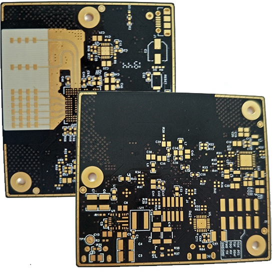
A Duroid PCB refers to a printed circuit board fabricated using RT/duroid high frequency materials, typically produced by Rogers. RT/duroid laminates are PTFE-based (Polytetrafluoroethylene) composites, designed specifically for microwave and RF applications that require extremely low signal loss and stable dielectric constant (Dk).
Compared to standard PCB materials, Duroid PCB offers strong advantages for high frequency circuits:
-
Ultra-low dielectric loss for reduced insertion loss
-
Stable dielectric constant (Dk) for reliable impedance control
-
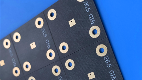
Excellent performance at GHz and mmWave frequencies
-
Strong suitability for RF trace PCB and microwave transmission lines
-
High reliability for critical RF systems
For high-end RF engineering, Duroid PCB is considered one of the most trusted material options.
Why Duroid PCB Is Ideal for RF and Microwave Circuits
1. Ultra-Low Loss Performance
One of the biggest reasons designers choose Duroid PCB is its ultra-low loss behavior at high frequencies. When signals travel through RF traces and transmission lines, dielectric loss and conductor loss can cause attenuation. Duroid PCB helps minimize dielectric loss, improving signal efficiency and performance.
This is especially important for:
-
Microwave amplifiers and filters
-
RF power distribution networks
-
Antenna feed lines
-
mmWave front-end modules
-
Low loss RF transmission lines
Lower loss means better system gain, improved sensitivity, and higher overall RF efficiency.
2. Stable Dielectric Constant for Controlled Impedance
Controlled impedance is a key requirement in RF PCB and microwave PCB design. Any Dk instability can result in impedance mismatch, reflections, and degraded return loss performance.
Duroid PCB provides stable dielectric properties, enabling accurate and repeatable:
-
50Ω single-ended impedance
-
75Ω RF impedance lines
-
RF transmission line structures such as microstrip and stripline
This stability helps designers achieve consistent RF performance across different production batches.
3. Excellent High Frequency Signal Integrity
At high frequencies, signal integrity becomes increasingly sensitive to material selection, stack-up design, and PCB manufacturing control. Duroid PCB supports high frequency signal integrity by reducing loss, minimizing phase distortion, and enabling clean transmission characteristics.
For high frequency signal PCB designs, Duroid PCB improves:
-
Insertion loss performance
-
Return loss behavior
-
Phase stability
-
High frequency consistency
This is critical for radar, satellite, and precision measurement systems.
Common Duroid PCB Applications
Because Duroid PCB offers outstanding RF performance, it is widely used in demanding applications such as:
-
5G and mmWave communication systems
-
Radar systems and automotive radar modules
-
Satellite communication and GPS devices
-
Antenna modules and phased array antennas
-
RF filters, couplers, and power dividers
-
High frequency test and measurement equipment
-
Aerospace and defense microwave electronics
In these systems, Duroid PCB helps maintain stable RF signal performance under strict requirements.
Duroid PCB vs FR-4 PCB: Key Differences
Although FR-4 is widely used for general electronics, it often becomes a limitation in RF and microwave circuits. Duroid PCB is designed specifically to solve high frequency challenges.
Duroid PCB advantages over FR-4 include:
-
Lower dielectric loss for better RF efficiency
-
More stable Dk for accurate impedance control
-
Improved signal integrity at GHz and mmWave frequencies
-
Better performance for RF trace routing and microwave transmission lines
If your design involves high frequency signals, Duroid PCB is typically the better choice to ensure performance stability.
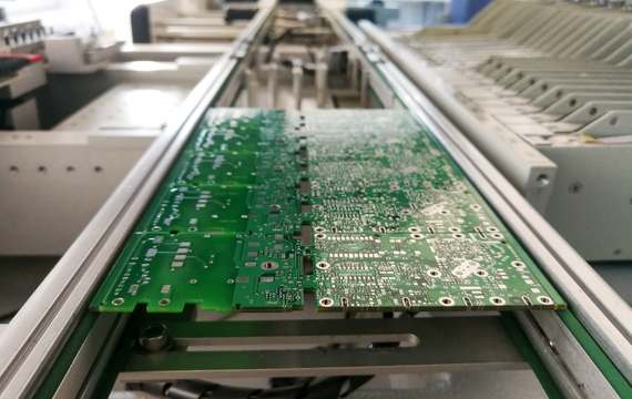
Duroid PCB Manufacturing Considerations
Manufacturing Duroid PCB requires more advanced PCB processing than standard FR-4 due to PTFE-based material characteristics. To ensure consistent quality and reliable RF performance, several key factors must be controlled during fabrication.
Important Duroid PCB manufacturing points include:
-
Accurate stack-up planning for controlled impedance PCB designs
-
Specialized lamination and bonding process control
-
Precise drilling and via quality management
-
Copper surface and roughness control for low loss performance
-
High reliability plating for demanding RF applications
-
Hybrid stack-up capability when combining Duroid with FR-4 materials
Choosing an experienced Duroid PCB manufacturer is essential for achieving stable electrical performance and high production consistency.
How to Improve Duroid PCB RF Performance
To get the best results from Duroid PCB designs, engineers often focus on both material selection and layout optimization. For high frequency RF circuits, key design recommendations include:
-
Maintain consistent trace width for controlled impedance
-
Minimize sharp corners and avoid unnecessary stubs
-
Optimize ground reference planes for stable return paths
-
Use proper via transitions and RF via stitching
-
Ensure correct stack-up thickness for impedance accuracy
-
Consider hybrid stack-up solutions for cost optimization
By combining good RF design practices with Duroid PCB material advantages, you can achieve excellent high frequency performance.
Conclusion
Duroid PCB is a proven and widely trusted solution for high frequency and microwave circuit designs. With ultra-low loss performance, stable dielectric constant, and excellent controlled impedance capability, Duroid PCB enables reliable operation in advanced RF applications such as 5G/mmWave systems, radar modules, satellite communication, and antenna networks.
If your project requires high frequency signal stability, low insertion loss, and consistent RF performance, Duroid PCB is an excellent choice for your next RF PCB or microwave PCB design.
