
Engineering Context
The rapid expansion of wireless communication, aerospace electronics, radar systems, and high-frequency semiconductor applications has created increasing demand for PCB materials with extremely stable electrical performance. At microwave and mmWave frequencies, conventional FR-4 materials often cannot provide sufficient dielectric stability, low signal loss, and phase consistency required for advanced RF systems.
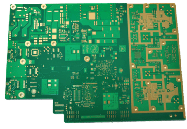
Rogers RT/duroid® 5880 PCB is widely recognized as a high-performance PTFE-based laminate designed for applications requiring ultra-low dielectric loss, excellent frequency stability, and consistent electrical characteristics. With a low dissipation factor and stable dielectric constant, this material enables reliable signal transmission in demanding RF and microwave environments.
Modern high-frequency systems including:
- Satellite communication payloads
- 5G base stations
- Radar modules
- RF transceivers
- Microwave amplifiers
- Aerospace communication equipment
- mmWave test platforms
require PCB structures capable of maintaining:
- Low insertion loss
- Precise impedance matching
- Stable phase response
- Low EMI interference
- High-frequency signal integrity
For engineers designing RF front-end systems, material selection directly influences system efficiency, communication range, and calibration requirements. For procurement teams, selecting a PCB manufacturer with experience in PTFE processing, controlled lamination, and RF verification is essential to ensure production consistency.
KKCPB specializes in advanced Rogers RT/duroid® 5880 PCB manufacturing, providing RF engineering support, high-frequency stackup optimization, controlled impedance fabrication, and reliability validation for global communication and aerospace customers.
Core Engineering Challenges
| Engineering Challenge | Root Cause | Engineering Impact |
|---|---|---|
| High-frequency insertion loss | Dielectric loss and copper roughness | Reduced RF efficiency and transmission range |
| Phase instability | Dk variation and thermal expansion | Signal timing errors and calibration drift |
| Impedance mismatch | Manufacturing tolerance variation | Reflection and signal degradation |
| EMI coupling | Dense RF routing and insufficient isolation | Crosstalk and interference |
| PTFE processing difficulty | Material softness and dimensional instability | Manufacturing yield reduction |
| Thermal deformation | CTE mismatch between materials | Layer registration errors |
These challenges become especially critical in Microwave PCB, mmWave PCB, Satellite Communication PCB, and RF Transceiver PCB applications where even small electrical variations can affect system performance.
Material Science & Dielectric Performance of Rogers RT/duroid® 5880 PCB
Rogers RT/duroid® 5880 is a glass microfiber reinforced PTFE composite engineered for high-frequency applications.
Its electrical properties remain stable across a wide frequency range, making it suitable for microwave and mmWave circuits.
Rogers RT/duroid® 5880 Material Parameters
| Parameter | Typical Value | Engineering Benefit |
|---|---|---|
| Dielectric Constant (Dk) | 2.20 ±0.02 | Stable impedance and phase performance |
| Dissipation Factor (Df) | 0.0009 @10GHz | Extremely low insertion loss |
| Thermal Conductivity | ~0.20 W/m·K | Supports moderate thermal loads |
| CTE X/Y | 17 ppm/°C | Maintains dimensional stability |
| Moisture Absorption | <0.02% | Stable electrical properties |
| Operating Temperature | High temperature capability | Reliable RF operation |
Comparison with Conventional PCB Materials
| Material | RF Performance | Typical Application |
|---|---|---|
| FR-4 PCB | Medium loss | General electronics |
| RO4003C PCB | Low loss | RF communication modules |
| RO4350B PCB | Low loss/high reliability | 5G and wireless systems |
| Duroid 5880 PCB | Ultra-low loss | Microwave and mmWave systems |
| Ceramic PCB | High thermal performance | High-power RF applications |
Compared with standard PCB materials, Duroid 5880 PCB provides superior dielectric stability, lower signal attenuation, and improved phase consistency for advanced RF designs.
RF Design Considerations for Rogers RT/duroid® 5880 PCB
Controlled Impedance Optimization
High-frequency transmission requires precise impedance control.
KKCPB engineering processes include:
- Microstrip optimization
- Stripline design
- Differential impedance calculation
- Copper roughness consideration
- Dielectric thickness control
- TDR verification
Typical RF impedance requirements:
| Circuit Type | Target Impedance |
|---|---|
| RF Transmission Line | 50Ω |
| Differential RF Signal | 100Ω |
| Microwave Interface | 50Ω |
Low-Loss Transmission Design
At GHz frequencies, conductor loss and dielectric loss directly affect system performance.
Engineering optimization includes:
- Low-profile copper foil selection
- Smooth copper surface treatment
- Optimized trace geometry
- Reduced unnecessary via transitions
These methods help minimize:
- Insertion loss
- Return loss
- Signal attenuation
EMI Control Strategy
Advanced RF systems often integrate digital control, power circuits, and high-frequency channels within limited PCB space.
KKCPB applies:
- Ground via fencing
- RF isolation zones
- Controlled return paths
- Shielding structures
- Layer separation techniques
to reduce electromagnetic interference and improve signal reliability.
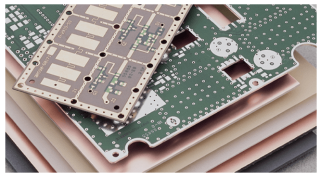
KKCPB Case Study — Rogers RT/duroid® 5880 PCB for Satellite Communication Transceiver Module
Client & Application Context
A North American aerospace communication company required a high-frequency PCB solution for a Ku-band satellite communication transceiver.
The module included:
- RF receiver chain
- Low-noise amplifier
- Power amplifier interface
- Frequency conversion circuits
- Antenna feed network
The customer required extremely low signal loss and stable phase performance during long-duration satellite operation.
Engineering Problem
The original PCB design used a standard microwave laminate but encountered several issues:
- Higher insertion loss at Ku-band frequency
- Phase variation between RF channels
- Increased calibration requirements
- Signal degradation during temperature variation
Measured issues included:
- Insertion loss exceeding design target
- Impedance variation above ±5%
- Phase deviation approaching 1.5°
The customer required a more stable RF PCB solution for production deployment.
KKCPB Engineering Solution
KKCPB developed a customized Rogers RT/duroid® 5880 PCB solution.
Material Selection
Implemented:
- Rogers RT/duroid® 5880 laminate for RF layers
- Controlled copper roughness
- Precision dielectric thickness control
Stackup Optimization
Designed:
- Dedicated RF signal layers
- Continuous ground reference layers
- Optimized dielectric spacing
- Reduced via transitions
Manufacturing Control
Applied:
- Vacuum lamination process
- Precision drilling
- Controlled PTFE fabrication process
- Automated electrical testing
Simulation & Verification
Performed:
- HFSS electromagnetic simulation
- ADS RF circuit simulation
- TDR impedance testing
- VNA S-parameter measurement
- Thermal FEM analysis
Measured Results
| Parameter | Target Requirement | KKCPB Result |
|---|---|---|
| Impedance Variation | ±5% | ±1.7% |
| Insertion Loss @18GHz | <0.35 dB/in | 0.22 dB/in |
| Phase Deviation | <1° | 0.42° |
| Return Loss (S11) | < -15dB | -19.5dB |
| Dielectric Thickness Tolerance | ±10μm | ±5μm |
| RF Channel Consistency | Required | Passed |
Project Outcome
The Rogers RT/duroid® 5880 PCB solution delivered:
- Lower RF transmission loss
- Improved phase consistency
- Reduced calibration complexity
- Enhanced communication reliability
- Better production repeatability
The PCB platform was successfully integrated into satellite communication equipment.
Stackup Design & RF Implementation
Representative 6-Layer Rogers RT/duroid® 5880 PCB Stackup
| Layer | Function | Material |
|---|---|---|
| L1 | RF Signal Layer | Rogers RT/duroid® 5880 |
| L2 | Ground Plane | Copper |
| L3 | Control Signal Layer | High TG FR-4 |
| L4 | Power Distribution | Copper |
| L5 | RF Signal Layer | Rogers RT/duroid® 5880 |
| L6 | Mechanical Layer | High Reliability PCB |
Simulation & Validation
HFSS Electromagnetic Simulation
Used for:
- RF field distribution
- Transmission line optimization
- EMI coupling analysis
ADS Circuit Simulation
Used for:
- RF circuit modeling
- Gain analysis
- Frequency response prediction
TDR Testing
Used for:
- 50Ω impedance verification
- Manufacturing consistency control
VNA Testing
Measured:
- S-parameters
- Return loss
- Insertion loss
Thermal FEM Simulation
Evaluated:
- Temperature distribution
- Material expansion effects
- RF performance stability
These combined simulation and measurement methods ensure reliable RF performance before mass production.
Environmental & Reliability Validation
| Test | Condition | Result |
|---|---|---|
| Thermal Cycling | -55°C ↔ +125°C, 1000 cycles | No delamination |
| Humidity Test | 85°C / 85% RH | Stable dielectric performance |
| Vacuum Test | Aerospace environment | Passed |
| Vibration Test | 5–500Hz, 10G | No mechanical failure |
| Solder Reflow | 260°C ×3 cycles | No warpage |
| RF Performance Test | Continuous operation | Stable insertion loss |
These reliability tests confirm the suitability of Rogers RT/duroid® 5880 PCB solutions for demanding aerospace and high-frequency communication applications.
Engineering Summary
Advanced RF systems require PCB solutions with excellent dielectric stability, low signal loss, precise impedance control, and reliable manufacturing performance.
Rogers RT/duroid® 5880 PCB provides outstanding advantages for microwave and mmWave applications due to its ultra-low dissipation factor, stable dielectric constant, and excellent phase consistency.
KKCPB provides professional high-frequency PCB manufacturing services including:
- Rogers RT/duroid® 5880 PCB fabrication
- RF and microwave PCB design support
- Controlled impedance PCB manufacturing
- mmWave PCB solutions
- Satellite communication PCB
- RF transceiver PCB
- High-frequency prototype and mass production
With advanced RF engineering capability, precision fabrication processes, and complete validation systems, KKCPB helps global engineers and procurement teams develop reliable high-frequency communication products with consistent electrical performance.
