
Single-chip microcontroller (MCU) control boards are widely used in industrial automation, consumer electronics, automotive systems, medical devices, smart sensors, and embedded control applications.
Although MCU-based systems are relatively compact compared with complex computing platforms, their PCB design still requires careful engineering consideration. Factors such as power stability, clock signal quality, reset reliability, electromagnetic compatibility (EMC), and manufacturing feasibility directly affect the performance and reliability of the final product.
A well-designed MCU control board should not only ensure correct circuit operation but also provide stable performance under different operating environments.
This article introduces key PCB design principles for single-chip microcontroller control boards, helping engineers improve design reliability and production readiness.
1. Understanding the Functional Structure of MCU Control Boards
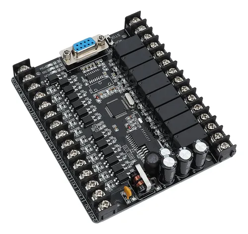
Before starting PCB layout, engineers should understand the functional blocks of the microcontroller system.
A typical MCU control board includes:
- Microcontroller unit (MCU)
- Power supply circuit
- Clock circuit
- Reset circuit
- Input/output interfaces
- Communication modules
- Sensor interfaces
- Programming and debugging interfaces
Each functional block has different design requirements.
Proper partitioning helps:
- Reduce signal interference
- Simplify routing
- Improve debugging efficiency
- Enhance system reliability
2. Power Supply Design for MCU Control Boards
Stable power supply is one of the most important factors in MCU PCB design.
Power fluctuations or excessive noise may cause:
- Unexpected resets
- Communication errors
- Program execution failures
- System instability
2.1 Power Plane Optimization
For multilayer PCB designs, dedicated power and ground layers can provide:
- Lower impedance paths
- Better current distribution
- Reduced noise coupling
For two-layer PCB designs, careful routing of power traces and ground connections is required.
2.2 Decoupling Capacitor Placement
Decoupling capacitors should be placed as close as possible to MCU power pins.
Their functions include:
- Filtering high-frequency noise
- Stabilizing local voltage
- Providing transient current
Common design practices include:
- Small-value capacitors near power pins
- Larger bulk capacitors near the power input
3. Clock Circuit Design Considerations
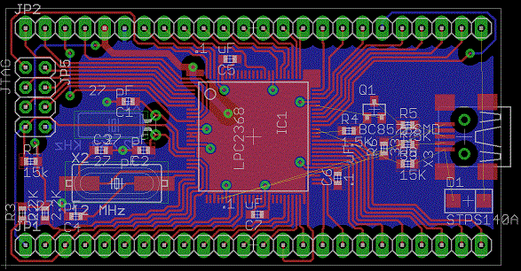
The clock circuit determines the operating timing of the MCU.
Poor clock layout may lead to:
- Frequency instability
- Timing errors
- Communication failures
Important design considerations include:
Short Crystal Connections
The crystal oscillator and related components should be placed close to the MCU.
Short connections help reduce:
- Noise coupling
- Parasitic capacitance
- Signal distortion
Avoid High-Noise Areas
Clock traces should be kept away from:
- Switching power circuits
- High-current paths
- Fast switching signals
This reduces interference and improves clock stability.
4. Reset Circuit Reliability Design
The reset circuit ensures that the MCU starts correctly and operates reliably.
Design considerations include:
- Proper pull-up or pull-down resistors
- Noise filtering
- Short reset signal routing
An unstable reset circuit may cause:
- Startup failures
- Random system resets
- Unpredictable behavior
For industrial and automotive applications, reset reliability becomes especially important.
5. PCB Layout Principles for MCU Control Boards
5.1 Functional Area Separation
A clear PCB layout should separate different functional areas.
Typical partitions include:
- Digital processing area
- Analog sensor area
- Power conversion area
- Communication interface area
This helps reduce interference between different circuits.
5.2 Keep Critical Signals Short
Critical signals should have optimized routing paths.
Examples include:
- Clock signals
- Reset signals
- High-speed communication lines
- Analog measurement signals
Shorter routing reduces:
- Noise pickup
- Signal delay
- Crosstalk
6. Grounding Design for MCU Systems
Grounding plays an important role in MCU PCB performance.
A poor grounding design may cause:
- ADC measurement errors
- Communication instability
- Increased EMI
Recommended practices include:
Continuous Ground Plane
A continuous ground plane provides:
- Low impedance return paths
- Better noise control
- Improved signal integrity
Analog and Digital Ground Management
For systems containing analog sensors and digital processing circuits, designers should carefully manage:
- Analog ground
- Digital ground
- Power ground
The connection strategy should be based on actual current flow and system requirements.
7. Communication Interface Design
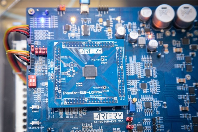
MCU control boards often include communication interfaces such as:
- UART
- SPI
- I²C
- CAN
- RS-485
- Ethernet
Each interface requires different PCB considerations.
High-Speed Communication
Important factors include:
- Controlled impedance
- Signal routing length
- Ground reference
- Noise protection
Industrial Communication Interfaces
For industrial environments, additional protection may be required:
- ESD protection
- Surge protection
- Isolation design
These measures improve system durability.
8. EMC and EMI Considerations
Microcontroller systems may generate electromagnetic interference due to:
- Clock signals
- Switching regulators
- Digital switching activities
EMC design practices include:
Reduce Signal Loop Area
Small current loops help reduce electromagnetic radiation.
Add Proper Filtering
Filtering components may be used for:
- Power inputs
- Communication interfaces
- External connections
Optimize Component Placement
Noise-generating components should be separated from sensitive circuits.
9. Design for Manufacturing (DFM) Considerations
A reliable MCU PCB design should consider manufacturing requirements from the beginning.
Important factors include:
Component Selection
Consider:
- Package availability
- Assembly requirements
- Long-term supply stability
PCB Manufacturing Rules
Design should consider:
- Minimum trace width and spacing
- Via structures
- Copper balance
- Solder mask requirements
Testing Requirements
Include:
- Programming interfaces
- Test points
- Debug access
This improves production efficiency and troubleshooting capability.
10. Reliability Design for Different Applications
Different industries have different requirements for MCU control boards.
Industrial Applications
Focus on:
- Long-term operation
- Noise resistance
- Temperature reliability
Automotive Applications
Require:
- Vibration resistance
- Thermal cycling reliability
- EMC performance
Medical Applications
Require:
- Stable signal processing
- High reliability
- Strict quality control
PCB design should be optimized according to the final application environment.
Conclusion
Designing a reliable PCB for a single-chip microcontroller control board requires careful consideration of power integrity, signal routing, grounding, EMC performance, thermal management, and manufacturing requirements.
Although MCU systems are relatively simple compared with advanced computing platforms, small design mistakes can significantly affect system stability and product reliability.
By following proper PCB design principles during the early development stage, engineers can reduce debugging challenges, improve production yield, and create more reliable embedded electronic products.
