
With the rapid development of industrial robotics, smart manufacturing, and automated production systems, robotic motion control technology has become increasingly important for achieving higher precision, speed, and efficiency.
The servo drive module is one of the core electronic units in robotic systems. It controls motor operation by precisely regulating:
- Position
- Speed
- Torque
- Acceleration and deceleration
A high-performance servo drive PCBA must simultaneously handle:
- High-current power conversion
- Real-time control signals
- Feedback processing
- Communication interfaces
- Thermal management
Compared with conventional motor control boards, robotic servo drive PCBAs require higher reliability due to continuous operation, rapid switching, and complex industrial environments.
This case study presents how KKPCB supported a robotic servo drive module PCBA project, addressing challenges related to power integrity, signal reliability, thermal performance, and production readiness.
1. Project Background
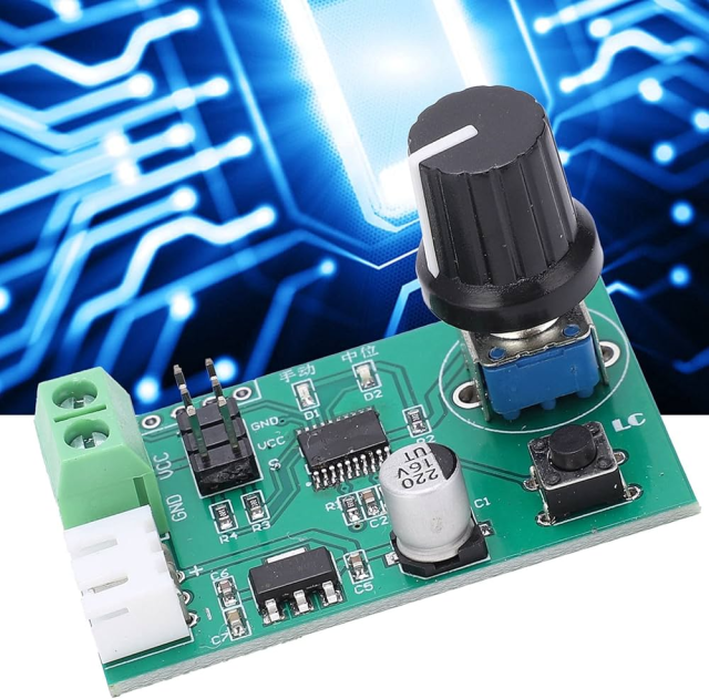
A customer developing an industrial robotic arm system required a customized servo drive module PCBA for controlling multi-axis robotic motion.
The servo drive module was designed to manage motor operation in applications requiring:
- High positioning accuracy
- Fast dynamic response
- Stable torque control
- Continuous industrial operation
The PCBA integrated multiple functional sections:
- Power conversion stage
- Motor control circuit
- Gate driver circuit
- MCU/DSP control unit
- Encoder feedback interface
- Industrial communication interface
The customer required a compact and reliable PCBA solution capable of supporting long-term operation in automated manufacturing environments.
During prototype validation, several PCB-level challenges were identified, including power switching noise, thermal stress, and manufacturing optimization.
2. Key Challenges in Robotic Servo Drive PCBA Development
Challenge 1: High-Current Motor Drive Reliability
Customer Pain Point
Servo drive modules must deliver high current to motors while maintaining stable operation.
The PCB needed to support:
- High-current power paths
- Rapid switching operation
- Low power loss
Potential problems included:
- Excessive voltage drop
- Copper overheating
- Reduced efficiency
- Component stress
The design required optimization of:
- Power trace width
- Copper thickness
- Current return paths
- Power loop structure
Challenge 2: Motor Control Signal Integrity
Customer Pain Point
Servo systems require accurate control signals for precise motion.
Sensitive signals included:
- PWM drive signals
- Encoder feedback signals
- Current sensing signals
Potential interference sources included:
- Switching power circuits
- Motor noise
- Electromagnetic radiation
Poor PCB layout could result in:
- Positioning errors
- Control instability
- Communication failures
Challenge 3: Gate Driver Circuit Optimization
Customer Pain Point
The gate driver controls power semiconductor switching behavior directly.
Improper design may cause:
- Switching losses
- Excessive ringing
- EMI increase
- MOSFET/IGBT stress
The PCB needed optimization of:
- Gate drive loop
- Driver power supply
- Isolation structure
- Signal return path
Challenge 4: Thermal Management Under Continuous Operation
Customer Pain Point
Industrial robots often operate continuously for extended periods.
Heat sources included:
- MOSFETs/IGBTs
- Power converters
- Motor drive components
Thermal issues could lead to:
- Reduced component lifetime
- Performance degradation
- System shutdown
The PCBA required effective:
- Heat dissipation paths
- Copper distribution
- Component placement strategy
Challenge 5: EMC Performance in Industrial Environments
Customer Pain Point
Robotic production lines contain multiple interference sources:
- Motors
- Inverters
- Switching power supplies
- Industrial communication equipment
The servo drive board needed strong resistance against:
- EMI interference
- Signal coupling
- Communication disturbance
3. KKPCB Engineering Support and Solutions
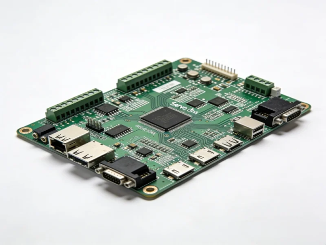
3.1 PCB Design Review and DFM Optimization
Before production, KKPCB engineering team conducted a comprehensive review focusing on:
- PCB stack-up
- Component placement
- Power routing
- Assembly feasibility
- Testing requirements
Optimization included:
- Improved component arrangement
- Enhanced manufacturability
- Added test accessibility
- Reduced production risks
The review helped the customer transition from prototype validation to stable production.
3.2 Power Stage Layout Optimization
To improve motor drive reliability, KKPCB optimized the power section design.
High-Current Routing Optimization
The engineering team reviewed:
- Power trace dimensions
- Copper thickness
- Current paths
Improvements helped achieve:
- Lower resistance losses
- Reduced voltage drop
- Better current handling capability
Switching Loop Optimization
The design reduced:
- High-frequency loop area
- Parasitic inductance
- Switching noise
Benefits included:
- Improved efficiency
- More stable power conversion
3.3 Gate Driver Circuit Improvement
The gate driver section was optimized through:
Shorter Driver Paths
Reducing:
- Signal delay
- Parasitic effects
- Switching instability
Improved Isolation Design
Considerations included:
- High-voltage separation
- Creepage distance
- Clearance requirements
Better Signal Return Paths
Optimization improved:
- Noise immunity
- Control signal stability
3.4 Motor Feedback Signal Optimization
For encoder and sensing circuits, PCB improvements included:
- Sensitive signal separation
- Improved grounding structure
- Reduced noise coupling
The optimization enhanced:
- Feedback accuracy
- Motion control stability
- System response
3.5 Thermal Management Optimization
The PCBA design considered:
- Power component placement
- Thermal copper areas
- Thermal vias
- Heat dissipation paths
These improvements supported:
- Continuous operation
- Better reliability
- Extended product lifetime
3.6 Communication Interface Reliability Improvement
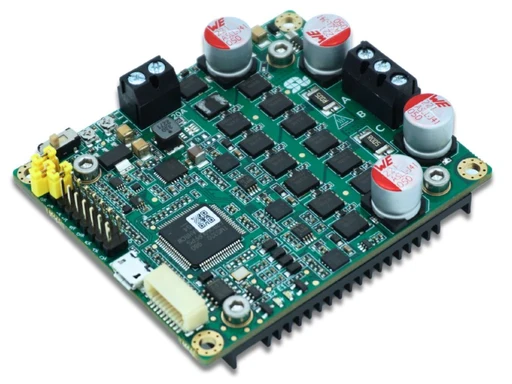
The servo drive module supported industrial communication functions such as:
- CAN bus
- RS-485
- Ethernet-based control interfaces
Optimization included:
- Interface protection
- Signal filtering
- EMC improvement
This improved communication stability between:
- Servo drive module
- Motion controller
- Industrial automation system
4. Manufacturing and Quality Control Process
PCB Fabrication
The servo drive PCBA required strict manufacturing control.
Key considerations included:
- Multilayer PCB structure
- High-Tg FR-4 material
- Heavy copper options
- Electrical isolation requirements
Manufacturing controls included:
- Layer alignment
- Copper thickness verification
- Hole reliability control
SMT and THT Assembly
The design combined:
SMT Components
Used for:
- MCU/DSP
- Driver ICs
- Sensor circuits
- Passive components
Through-Hole Components
Used for:
- Power connectors
- High-current terminals
- Large capacitors
Advantages:
- Mechanical strength
- High-current capability
Inspection and Testing
Quality control included:
SPI Inspection
Verification of:
- Solder paste printing quality
AOI Inspection
Checking:
- Component placement
- Solder defects
X-Ray Inspection
Used for:
- Hidden solder joints
- Power connections
Functional Testing
Validation included:
- Motor control response
- Current regulation
- Encoder feedback
- Communication stability
- Protection functions
5. PCB Technologies for Robotic Servo Drive Applications
5.1 Multilayer PCB
Advantages:
- Improved power distribution
- Better signal isolation
- Higher integration
Applications:
- Compact servo controllers
5.2 Heavy Copper PCB
Advantages:
- Higher current capability
- Better thermal performance
Applications:
- High-power motor drives
5.3 High-Tg PCB
Advantages:
- Improved thermal reliability
- Better mechanical stability
Applications:
- Industrial environments
5.4 Controlled Impedance PCB
Advantages:
- Improved signal integrity
Applications:
- High-speed communication interfaces
6. Applications of Similar Servo Drive PCBA Solutions
Industrial Robots
Applications:
- Robotic arms
- Multi-axis robots
- Collaborative robots
Automated Production Equipment
Applications:
- CNC machines
- Assembly lines
- Precision manufacturing equipment
AGV and Mobile Robots
Applications:
- Autonomous vehicles
- Warehouse robots
Semiconductor Equipment
Applications:
- Precision motion platforms
- Automated handling systems
7. Project Results
Through PCB design optimization and manufacturing support, the robotic servo drive PCBA achieved:
- Improved power stability
- Enhanced motor control reliability
- Better thermal performance
- Improved production consistency
Validation results included:
- 98%+ first-pass production yield
- Reduced debugging time during system integration
- Improved long-term operational stability
8. Key Engineering Insights
8.1 Servo Drive Performance Depends on PCB-Level Optimization
A reliable servo system requires more than advanced motor algorithms.
PCB design directly affects:
- Power efficiency
- Control accuracy
- EMI performance
- System lifetime
8.2 Power and Signal Integrity Must Be Designed Together
Servo drive PCBAs contain both:
- High-power switching circuits
- Sensitive control signals
Successful designs require careful management of:
- Current paths
- Grounding
- Signal separation
- Noise control
8.3 Manufacturing Capability Is Critical for Industrial Reliability
High-performance servo PCBAs require consistent manufacturing processes, including:
- Precise assembly
- Reliable solder joints
- Functional testing
Early DFM analysis helps reduce production risks.
Conclusion
Robotic servo drive PCBAs are essential components for achieving precise and reliable motion control in industrial automation systems.
A successful solution requires comprehensive engineering consideration of:
- High-current power design
- Gate driver optimization
- Signal integrity
- Thermal management
- EMC performance
- Manufacturing reliability
In this project, KKPCB supported the customer through PCB design optimization, power integrity improvement, thermal management enhancement, DFM analysis, and production process control, helping transform a robotic servo drive design into a reliable and manufacturable industrial solution.
As robotics continues moving toward higher precision, greater integration, and smarter automation, advanced PCBA solutions will remain a key foundation for next-generation motion control systems.
