
Safety-related automation boards are often judged by the relay or isolator chosen in the schematic, while the real risk sits in the geometry around it. A mounting standoff enters a clearance zone, a slot is omitted during panelization, or flux residue bridges a high-potential region after assembly. An Industrial Automation PCB used for a safety relay, machine interlock, or mains-to-control interface must make creepage, clearance, protective earth, and inspection access visible before procurement starts.
An Industrial Automation PCB safety review should name the enclosure, service action, and inspection sequence before the layout is frozen.
This article focuses on the release problem faced by engineers and project managers: how to move from a nominal isolation concept to a board that can be built, inspected, installed, and reworked without silently changing the safety boundary. The dimensions and limits must be set against the applicable product standard and working environment; the workflow below is an engineering control method, not a certification claim.
- Separate high-voltage, protective-earth, and low-voltage control zones.
- Use slots, keep-outs, and mounting hardware deliberately, not decoratively.
- Define cleaning, coating, inspection, and rework rules with the assembly data.
- Release hipot, insulation, continuity, and enclosure-fit evidence under one revision.
Table of contents
For an Industrial Automation PCB, the safety zone map is the bridge between schematic intent and manufacturable geometry.
Define the safety zones before routing
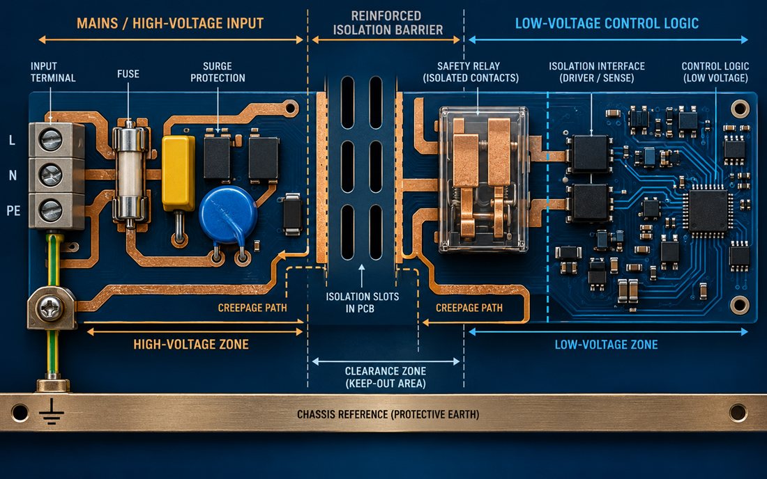
The first step for an Industrial Automation PCB is a zone map. Draw the mains or high-voltage input, the protective-earth path, the relay contact region, the isolation barrier, and the low-voltage controller area. Include the board edge, mounting holes, terminal screws, test pads, and any shield or heat spreader that could become conductive. A zone map gives the PCB materials and fabrication teams a common reference before a dense placement begins.
Do not let the low-voltage plane run under a relay contact simply because the inner layer is hidden. A plane cut, slot, or keep-out can be needed to maintain the intended path through the board. Mark the no-copper region in the layer data and in the assembly drawing. If an enclosure adds a metal bracket or spring, place that hardware on the same zone map instead of treating it as a mechanical afterthought.
Make protective earth a real conductive feature
Protective earth is not the same as signal ground. Give the PE terminal, chassis contact, and any shield bond a defined path that can be inspected and serviced. A high-frequency PCB perspective is useful because a short chassis path also reduces the impedance of fast common-mode events. At the same time, keep PE current away from the sensor reference and logic return unless the design explicitly defines their relationship.
Where a metal enclosure is painted, specify the conductive contact area or hardware that removes the coating at the bond. A plated mounting hole is not automatically a safety-earth connection if the screw, washer, and cabinet surface are insulated. Put the contact requirement in the drawing and inspection plan, not only in a design review note.
An Industrial Automation PCB is only as robust as the clearance and creepage features that survive routing, panelization, and inspection.
Turn clearance and creepage into reproducible geometry
Clearance is the shortest through-air distance; creepage follows the surface. Both are affected by slots, ribs, solder mask, contamination, component body, and mounting hardware. The PCB manufacturing package should show slots, edge distances, drill tolerances, and copper keep-outs in a way that the fabricator can inspect. Avoid relying on a dimension that disappears when the board is panelized or routed.
Use slots when the applicable design analysis calls for a longer surface path, but check that the slot can be drilled, routed, cleaned, and inspected. A narrow slot may collect debris or be partially closed by a routing burr. A broad keep-out is easier to inspect but consumes area that may be needed for thermal spreading. The choice is an engineering trade, not a decorative pattern.
Keep component and mounting choices inside the boundary
Relay housings, optocouplers, fuses, terminals, standoffs, and heat sinks all have conductive or capacitive influence. A package with a molded barrier may still require board spacing around its leads. A metal standoff near a slot can shorten the effective path. The PCB assembly traveler should call out orientation, polarity, barrier keep-outs, and the inspection method for parts that define the safety function.
If a coating is proposed, verify that the product standard allows it to be considered in the intended insulation system. Coating may protect against moisture, but it does not excuse a geometry that fails before coating. It also introduces masking, cure, thickness, and rework decisions. Put coating boundaries on the board and panel drawings so the assembler does not interpret a generic note differently on each lot.
The Industrial Automation PCB assembly process must preserve the isolation boundary after soldering, cleaning, coating, and rework.
Protect the isolation boundary through assembly
Cleaning and handling can change insulation performance even when the copper geometry is correct. Define the flux process, cleaning agent, ionic contamination control, and drying method that apply to the safety region. The fabrication release should identify exposed copper, slots, and edge conditions that must remain free of burrs or residues after routing.
Keep test pads accessible without forcing a probe to cross an unsafe region. If a production fixture needs a high-potential connection, provide a dedicated guarded point and a controlled sequence. The surface finish should be selected for solderability, corrosion exposure, and any repeated contact at the safety terminal; do not assume the finish alone determines insulation performance.
Use inspection gates that match the risk
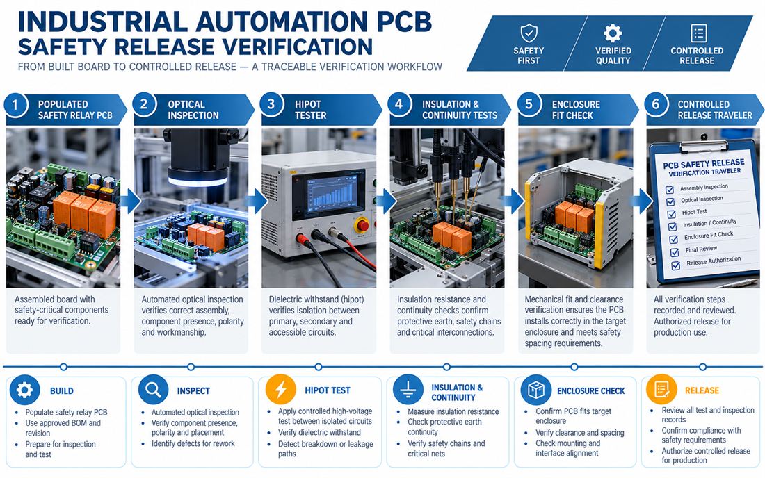
Optical inspection can confirm component presence, polarity, slot condition, and visible contamination. It cannot replace a dielectric withstand or insulation-resistance check. Define what each gate proves and what it cannot prove. A Industrial Automation PCB should check whether the intended inspection tools can reach the barrier and whether the panel rails hide a critical edge.
When a safety relay is reworked, the disposition should record the affected zone, component lot, cleaning action, and retest. This is especially important when a relay contact or isolator is replaced near a slot. A board that looks identical after rework may have a different residue or solder fillet condition at the very location that carries the safety function.
An Industrial Automation PCB safety release is a cross-functional package, not only a dielectric test result.
Build a traceable safety release package
A safety release is stronger when drawing, BOM, assembly traveler, test fixture, and enclosure model share one revision. The board should be fitted in the real cabinet before final approval so terminal access, protective-earth contact, and service clearances are not assumed. A controlled prototype PCB can expose these issues early, provided it uses the intended stack, finish, mounting hardware, and barrier geometry.
Separate design targets from test results
The release record can state a design target, a test method, and an acceptance decision without inventing a customer measurement. Record the approved test voltage and duration from the applicable requirement, the instrument identification, the fixture wiring, and the disposition of any failure. The assembly fixture should prevent a low-voltage probe from being connected to the wrong net and should retain the board revision with the test record.
| Gate | Question | Controlled evidence |
|---|---|---|
| Geometry | Are clearance, creepage, slots, and mounting features consistent? | Layer drawings, drill data, and enclosure fit check |
| Assembly | Are components, cleaning, coating, and rework rules unambiguous? | Traveler, inspection criteria, and deviation log |
| Electrical | Do hipot, insulation, continuity, and PE checks follow the approved sequence? | Fixture wiring and signed test record |
| Change control | Can an alternate part change the boundary or contact path? | Approved substitution review and revision history |
Freeze the safety boundary before approving a substitute
The Industrial Automation PCB purchase release should retain the approved relay, barrier, earth hardware, and test fixture assumptions.
Before purchasing the next lot of an Industrial Automation PCB, freeze the isolation geometry, relay or isolator package, terminal, earth hardware, coating intent, and test fixture. A replacement component with the same voltage rating may have a different body, lead pitch, or creepage path. Attach the approved PCB manufacturing data and the Industrial Automation PCB assumptions to the purchase release so the change can be evaluated instead of accepted by part number alone.
An Industrial Automation PCB design is safety-ready when its high-voltage zone, protective-earth path, low-voltage zone, assembly controls, and release evidence tell the same story. A pilot build can then confirm the mechanical and inspection details before volume manufacturing.
The Industrial Automation PCB handoff is strongest when geometry, assembly controls, and verification evidence agree.
Sources: Analog Devices isolation and industrial interface guidance; Würth Elektronik grounding, connector, and assembly notes; Qorvo protection and interface references; relay, isolator, coating, and PCB material supplier application data. The diagrams are original conceptual engineering graphics and do not represent a customer measurement, certification, or qualification report.
