
A servo drive can deliver the right torque and still fail the machine if its encoder feedback arrives with the wrong phase, a moving reference, or an intermittent shield bond. In a compact drive, motor switching currents, isolated power, feedback pairs, and the cabinet return path share very little space. An Industrial Automation PCB for servo control therefore has to preserve signal integrity while handling the thermal and mechanical stress of a motor cable that is repeatedly flexed or routed beside power conductors.
An Industrial Automation PCB servo review should begin with the encoder cable, motor return, and service connector rather than only the drive IC.
The most expensive failures are intermittent: a position alarm appears only at a certain speed, a homing cycle occasionally reverses, or a replacement cable changes the noise margin. This review gives the hardware and project teams a way to make the encoder interface, return path, connector launch, and production test agree before the drive is released.
- Separate motor switching current from encoder return current.
- Route A/B/Z differential pairs with a defined reference and connector datum.
- Bond the cable shield at the intended chassis point without using it as signal 0 V.
- Verify phase, polarity, strain relief, and isolation with the actual cable.
Table of contents
For an Industrial Automation PCB, motor power and encoder reference are separate design regions with one controlled relationship.
Keep the motor power zone from owning the encoder reference
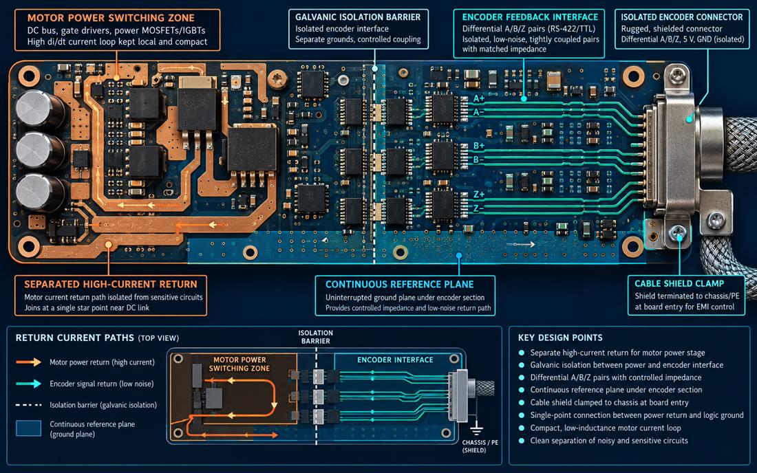
The first layout decision for an Industrial Automation PCB is to define where the DC bus, gate drivers, and motor return currents circulate. Those loops should be compact and remain on the power side of the board. The encoder interface needs its own quiet region and a controlled transition to the isolated controller ground. A power plane that runs continuously under the connector may look convenient, but it can carry switching energy into the feedback reference.
Use physical boundaries, not only net names. Put the isolated DC/DC converter, digital isolator, and feedback receiver on the boundary, then show the expected current path in the review drawing. The PCB materials stack and copper balance influence the impedance and thermal spreading of both regions. If a heavy copper layer is proposed for the motor stage, check how its geometry changes the distance and capacitance seen by the encoder pairs.
Reference the interface where the receiver actually measures it
Encoder receivers measure the voltage at their pins, not the voltage the designer intended at the connector. Keep the pair length, return vias, and termination components close to the receiver. A high-frequency PCB approach is useful because fast A/B edges and cable capacitance create a current path even when the encoder data rate appears modest. Avoid a long unreferenced run between the connector and the receiver package.
For an isolated feedback channel, decide whether the shield, signal return, and chassis bond are separate. The shield should normally terminate to chassis or PE at the chosen entry point; it should not become the low-voltage return for the receiver. If the cable includes a drain wire, define how it is clamped and how the clamp is inspected after assembly.
An Industrial Automation PCB preserves encoder phase by treating each differential pair and its return as one interface.
Route A/B/Z pairs as a matched interface
Keep A+ with A-, B+ with B-, and Z+ with Z- through the connector launch, protection components, and receiver. Match the exposure of each conductor to the reference plane and avoid a pair crossing a split created for the motor stage. Via transitions should be symmetric where possible, and any layer change should preserve a nearby return via. The PCB manufacturing drawing should identify the pair geometry or impedance intent only to the tolerance that the fabricator can control and inspect.
Protect the interface at the cable entry without adding excessive capacitance. A common-mode component can help, but its package, pad geometry, and placement determine whether it improves or degrades the edge. Put the protection decision in the schematic, layout review, and PCB assembly traveler so a substitute component does not move the reference or change the pair symmetry.
Control the isolated supply and logic reference
Encoder receivers often share a small isolated supply with other feedback or communication circuits. Place the converter return loop away from the pair entry and give the receiver a local decoupling path. If the isolated side is allowed to float, define the allowable capacitance to chassis and the point where test equipment can reference the circuit. A project that leaves those decisions implicit will often show different waveforms when the fixture ground clip is moved.
Thermal drift can also change receiver thresholds. Keep hot switching components and their copper spread away from the encoder input and any precision termination. The fabrication release should call out thermal vias, solder mask openings, and keep-outs that must remain reproducible through panelization and rework.
The Industrial Automation PCB connector launch is where the electrical, mechanical, and shield decisions meet.
Make connector and shield mechanics part of signal integrity
The connector launch is a mechanical datum as much as an electrical feature. A right-angle connector can move the shield clamp, change pair length, or force a bend that violates the cable supplier’s minimum radius. The Industrial Automation PCB should include mating force, latch access, strain relief, mounting screws, and the board edge. It is not enough to confirm that the footprint passes a library check.
Terminate the shield with a short, wide connection to the chassis reference. If the enclosure is painted, define the bare-metal contact or conductive hardware that makes the bond. The surface finish and exposed copper condition should match the contact system; a finish chosen for soldering alone may not be appropriate for a repeated shield spring or grounding pad.
Design for service without changing the return path
Service technicians need a way to disconnect the encoder cable without scraping the shield or touching an exposed high-voltage region. Reserve a probe point on the logic side and a clearly identified chassis test point. Keep the connector and shield hardware accessible after the board is mounted. A controlled prototype PCB should be evaluated inside the real drive housing so service access and cable bend are not guessed from a bench harness.
An Industrial Automation PCB is not servo-ready until the actual cable, shield, and measurement reference are verified together.
Verify phase, polarity, and cable behavior together
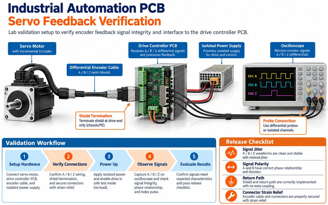
A productive servo test does not begin with a waveform screenshot. It begins with a wiring map: motor, encoder, shield, isolated supply, chassis, and measurement reference. Use the intended cable length and representative routing. Confirm A/B polarity, index pulse behavior, shield termination, connector strain relief, and the drive’s response to a controlled start and stop. The second figure in this article illustrates a conceptual fixture; it is a workflow, not a claim of measured customer performance.
Turn the verification into repeatable release evidence
Capture the board revision, cable identifier, receiver configuration, and fixture wiring on the same record. The assembly fixture should not rely on a technician remembering which probe is differential. Mark the channels and ground reference, then define what constitutes a wiring error, a shield-bond error, or a true board defect. This makes a field-return investigation faster and prevents a cable change from being misdiagnosed as firmware drift.
| Check | Engineering question | Release record |
|---|---|---|
| Pair integrity | Are A/B/Z pairs routed with the intended reference and polarity? | Layout review and connector pin map |
| Return path | Does encoder return remain separate from motor switching current? | Current-path sketch and continuity check |
| Shield bond | Is the cable shield clamped at the intended chassis datum? | Assembly photo and bond inspection |
| Mechanical service | Can the cable be removed without damaging the shield or board? | Fit and strain-relief check |
Freeze the feedback contract before approving alternates
The Industrial Automation PCB purchase release should preserve the approved encoder connector, pair geometry, and fixture wiring.
Before releasing the next lot of an Industrial Automation PCB, freeze the encoder connector, pair geometry, isolation device, shield rule, and test setup. A substitute connector may fit the holes but change the shield contact or pair launch. A different cable may fit the plug but change capacitance and bend force. The approved PCB manufacturing package and assembly traveler and Industrial Automation PCB assumptions should travel with the purchase release so a buyer can evaluate those changes deliberately.
An Industrial Automation PCB release is ready for a motion-control build when the motor return, encoder reference, shield bond, and service procedure are all visible in one revision-controlled package. That alignment preserves phase margin. A controlled pilot prototype exposes cable and shield interactions before volume release. and avoids turning an intermittent machine alarm into a long software investigation.
The Industrial Automation PCB handoff is strongest when phase, polarity, shield bond, and service access are visible in one revision package.
Sources: Analog Devices isolated interface and motor-control application guidance; Würth Elektronik connector, shielding, and assembly notes; Qorvo signal-integrity references; encoder, cable, isolation, and PCB material supplier application data. The diagrams are original conceptual engineering graphics and do not represent a customer measurement or qualification report.
