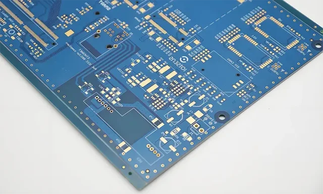
What is RO4003 PCB for 5G Antenna?
An RO4003 PCB for 5G antenna is a high-frequency printed circuit board manufactured using RO4003 laminate, widely used in RF and microwave applications.
RO4003 is a hydrocarbon ceramic material designed to provide low dielectric loss, stable electrical performance, and consistent impedance control, making it highly suitable for 5G antenna PCB designs.
In 5G systems, especially sub-6 GHz and certain mmWave antenna modules, RO4003 PCB plays a key role in ensuring efficient signal radiation and minimal transmission loss.
Why RO4003 PCB is Ideal for 5G Antenna
Designing a 5G antenna PCB requires materials that can maintain signal integrity at high frequencies. RO4003 PCB offers:
- Low dielectric constant (Dk ≈ 3.38) for stable signal propagation
- Low dissipation factor (Df ≈ 0.0027) for reduced signal loss
- Excellent consistency across frequency ranges
- Good manufacturability compared to PTFE materials
Key Electrical Properties of RO4003 PCB
1. Stable Dielectric Constant (Dk)
Ensures predictable impedance control in 5G antenna PCB layouts.
2. Low Dissipation Factor (Df)
Minimizes insertion loss, critical for antenna efficiency.
3. Frequency Stability
RO4003 PCB maintains consistent performance across high-frequency ranges.
4. Low Moisture Absorption
Improves long-term reliability in outdoor or harsh environments.
RO4003 PCB vs Other RF Materials
RO4003 PCB vs FR4
- RO4003 PCB → low loss, suitable for RF
- FR4 → higher loss, not suitable for 5G antenna
RO4003 PCB vs PTFE PCB
- RO4003 PCB → easier to manufacture
- PTFE PCB → lower loss but more complex processing
Applications of RO4003 PCB in 5G Antenna
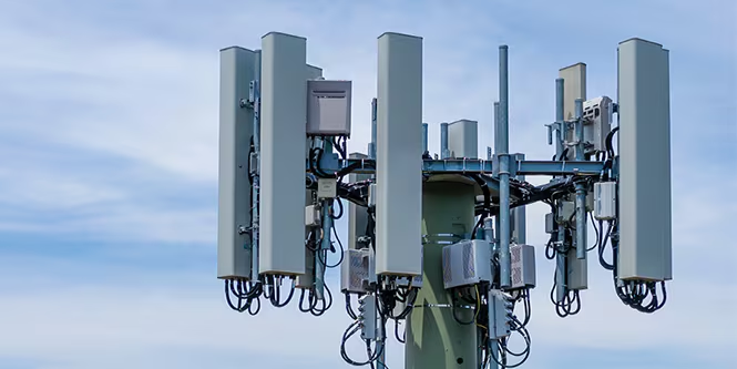
1. 5G Base Station Antennas
RO4003 PCB is widely used in antenna arrays and RF front-end modules.
2. Phased Array Antennas
Supports beamforming with stable signal performance.
3. Small Cell Antennas
Compact 5G antenna PCB designs benefit from RO4003 materials.
4. RF Modules
Used in integrated antenna and transceiver modules.
Design Considerations for RO4003 PCB in 5G Antenna
1. Controlled Impedance Design
RO4003 PCB must be designed with precise impedance for optimal antenna performance.
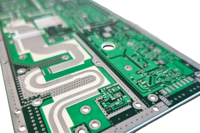
2. Trace Geometry Optimization
Trace width and spacing directly affect signal behavior in antenna circuits.
3. Ground Plane Integrity
Continuous ground reference is essential for stable RF performance.
4. Surface Roughness Control
Smooth copper reduces conductor loss in high-frequency designs.
Manufacturing Considerations
Producing RO4003 PCB for 5G antenna requires:
- Tight dielectric thickness control
- Accurate impedance fabrication
- Precision etching for RF traces
- Consistent material handling
Advantages of RO4003 PCB for 5G Antenna
- Lower signal loss compared to FR4
- Better manufacturability than PTFE
- Stable RF performance
- Cost-effective for medium-to-high frequency designs
When Should You Choose RO4003 PCB?
Choose RO4003 PCB when:
- Designing 5G antenna systems
- Working in sub-6 GHz to mid-frequency RF ranges
- Requiring stable impedance and low loss
- Balancing performance and cost
Avoid it when:
- Ultra-high frequency (mmWave) requires PTFE-level materials
- Thermal performance is the primary concern
Conclusion
RO4003 PCB is a proven material for 5G antenna PCB design, offering a strong balance between low loss, electrical stability, and manufacturability.
For engineers developing 5G antenna systems, RO4003 PCB provides a reliable and scalable solution for high-frequency applications.
