As data rates increase and electronic systems become more powerful, traditional PCB design approaches are no longer sufficient. High-speed interfaces such as PCIe, DDR memory, USB, and high-frequency communication systems require extremely precise signal control.
A High Speed PCB is specifically designed to handle fast signal transitions and high-frequency operation while maintaining signal integrity and minimizing noise.
Without careful design, high-speed signals can suffer from reflection, attenuation, and electromagnetic interference, which may lead to system instability or data errors.
What Is a High Speed PCB?

A High Speed PCB is a printed circuit board engineered to support high-frequency or high-data-rate signals, typically above several hundred megahertz or multi-gigabit per second data speeds.
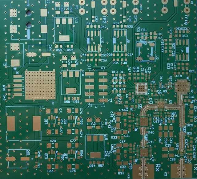
In high-speed circuits, PCB traces behave like transmission lines. This means factors such as impedance, propagation delay, and crosstalk must be carefully controlled.
Typical features of high-speed PCB designs include:
• controlled impedance traces
• differential pair routing
• multilayer stackups with dedicated ground planes
• low-loss dielectric materials
These techniques help ensure signals travel across the PCB accurately and reliably.
Key Design Considerations for High Speed PCB

Designing high-speed boards requires attention to multiple electrical and physical parameters.
Signal Integrity
Signal integrity refers to maintaining the quality of electrical signals as they travel through the PCB. Poor routing can cause distortion, jitter, or reflections.
Controlled Impedance
High-speed signals require specific impedance values, typically 50Ω for single-ended signals and 100Ω for differential pairs.
This ensures signals match the impedance of connected devices and transmission lines.
Crosstalk Reduction
Closely spaced traces can interfere with each other through electromagnetic coupling. Proper spacing and ground shielding reduce this effect.
Layer Stack-Up Design
High-speed PCBs often use multilayer structures with dedicated ground planes to maintain stable signal references.
Length Matching
For differential pairs or parallel buses, trace lengths must be carefully matched to ensure signals arrive at the same time.
Materials Used in High Speed PCBs
Material selection significantly affects signal performance.
Common high-speed PCB materials include:
Low-loss FR-4 variants
Improved dielectric properties compared with standard FR-4.
High-frequency laminates
Materials designed to minimize signal loss at high frequencies.
Advanced composite materials
Used in extremely high-speed or RF applications.
The dielectric constant (Dk) and loss tangent (Df) of the material directly influence signal propagation and attenuation.
Applications of High Speed PCBs
High-speed PCB technology is essential across multiple advanced electronics sectors.
Data Center Servers
High-speed processors and memory interfaces demand precise PCB routing.
Telecommunications Infrastructure
Networking equipment and 5G systems rely on high-speed signal transmission.
High-End Consumer Electronics
Gaming systems, graphics cards, and advanced computing devices use high-speed PCB designs.
Aerospace and Defense
Radar systems and communication equipment require high-frequency circuit boards.
Why High Speed PCB Design Is Critical
Modern electronics increasingly rely on fast data transmission and high-frequency operation. As signal speeds continue to rise, PCB design becomes a crucial factor in system performance.A well-designed High Speed PCB ensures reliable signal transmission, minimizes electromagnetic interference, and supports the demanding requirements of next-generation electronic systems.
In the world of advanced electronics, signal integrity begins with the PCB.
