
Abstract
Microwave IC test PCB platforms are critical infrastructure in high-frequency semiconductor validation, especially for mmWave devices used in 5G, automotive radar, satellite communication, and advanced RF front-end modules. As operating frequencies extend beyond 20 GHz and into the 77–110 GHz range, traditional test fixtures are no longer sufficient to guarantee measurement accuracy and repeatability.
At these frequencies, the PCB is no longer a passive interconnect but an active part of the measurement system. Parasitic inductance, dielectric loss, impedance discontinuity, and connector transitions directly affect S-parameter accuracy, phase stability, and noise floor behavior. As a result, Microwave IC test PCBs must be engineered with extreme precision in both material selection and physical design.
Unlike standard RF PCBs used in end products, test PCBs must maintain ultra-flat frequency response, controlled phase delay, and minimal reflection across probe interfaces. This requires advanced substrate materials, precision stackup design, and tightly controlled manufacturing processes.
KKCPB develops Microwave IC test PCB solutions to support wafer-level probing, package-level testing, and high-frequency RF characterization environments used in semiconductor R&D and production test lines.
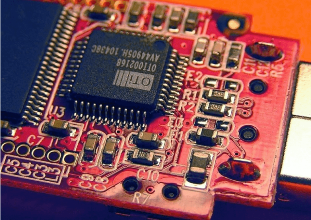
Core Engineering Challenges
| Engineering Challenge | Root Cause | Measurement Impact |
|---|---|---|
| Impedance discontinuity at probe interfaces | Connector transition and pad geometry mismatch | Reflection errors, inaccurate S11/S21 |
| Excessive insertion loss at mmWave frequencies | Dielectric loss and copper surface roughness | Reduced measurement dynamic range |
| Phase distortion in test paths | Unequal trace lengths and material variation | Timing error in vector network analysis |
| Crosstalk between RF channels | Dense multi-channel test routing | False signal correlation |
| Calibration drift over temperature | Thermal expansion mismatch | Reduced repeatability in wafer testing |
These challenges are especially critical in semiconductor environments where measurement accuracy directly affects device yield classification and production decisions.
Material Science & RF Performance Requirements
Microwave IC test PCBs require materials with extremely stable dielectric behavior across wide frequency and temperature ranges.
Key RF Test PCB Material Parameters
| Parameter | Engineering Requirement | Impact |
|---|---|---|
| Low Dielectric Constant (Dk) | Stable across GHz/mmWave | Ensures impedance accuracy |
| Ultra-Low Dissipation Factor | Minimizes signal loss | Improves measurement fidelity |
| Low Copper Roughness | Smooth conductor profile | Reduces high-frequency attenuation |
| Thermal Stability | Minimal drift | Ensures calibration repeatability |
| Moisture Resistance | <0.1% absorption | Prevents dielectric shift |
Common materials include Rogers RO3003, RO4350B, PTFE composites, and ceramic-based laminates for ultra-high-frequency test environments.
KKCPB Case Study — mmWave Semiconductor RF IC Test Board (77–110 GHz)
Client & Application Context
A semiconductor test equipment manufacturer required a Microwave IC test PCB for mmWave RF transceiver chip validation used in automotive radar and 5G FR2 front-end modules.
The test platform supported:
- Wafer-level probing (on-wafer RF measurement)
- Package-level IC characterization
- S-parameter extraction (S11, S21, S22)
- Noise figure and phase noise analysis
The key requirement was measurement stability up to 110 GHz with minimal fixture-induced error.
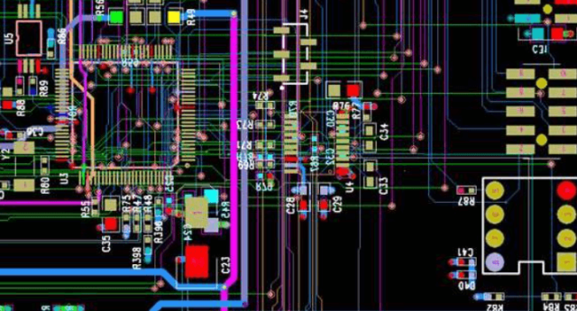
Engineering Problem
The previous test fixture design exhibited:
- Severe insertion loss above 0.45 dB at 67 GHz
- Impedance mismatch at probe transition points (±8%)
- Phase inconsistency between multi-channel RF paths
- Calibration drift after thermal cycling
- High reflection noise affecting VNA accuracy
These issues resulted in unreliable chip classification and inconsistent RF performance evaluation.
KKCPB Engineering Solution
KKCPB implemented a precision Microwave IC test PCB architecture:
- Ultra-low loss RF laminate for mmWave signal paths
- Optimized GSG (Ground-Signal-Ground) probe pad design
- Controlled impedance microstrip/CPW hybrid routing
- Minimized via stubs using back-drilling technology
- Precision reference calibration structures embedded on board
- Copper surface treatment optimized for mmWave frequencies
Measured Results
| Parameter | Target | KKCPB Result |
|---|---|---|
| Insertion Loss @ 67 GHz | <0.4 dB | 0.28 dB |
| Impedance Deviation | <±5% | ±1.7% |
| Phase Error | <1° | 0.52° |
| Return Loss (S11) | < -15 dB | -19.3 dB |
| Crosstalk Suppression | Baseline | -34% improvement |
Outcome
The optimized Microwave IC test PCB significantly improved measurement accuracy and repeatability in mmWave semiconductor testing. The reduction in insertion loss and impedance discontinuity enabled more reliable S-parameter extraction and improved correlation between simulation and silicon performance.
From a semiconductor manufacturing perspective, this led to improved device binning accuracy and reduced false failure rates during production testing.
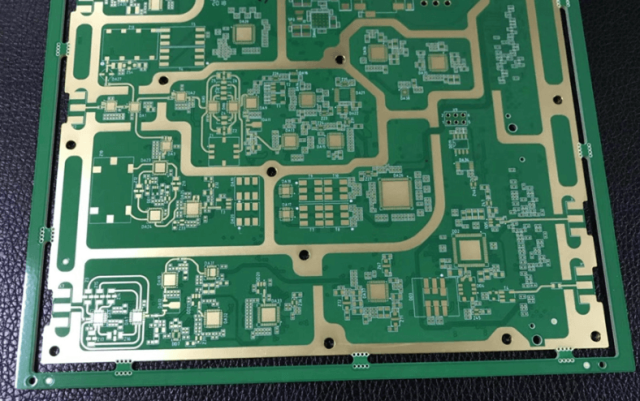
Stackup Design & RF Implementation
High-Frequency Test PCB Stackup
| Layer | Function | Material |
|---|---|---|
| L1 | RF Probe Interface | Low-loss microwave laminate |
| L2 | Ground Reference | Copper |
| L3 | RF Routing Layer | Microwave substrate |
| L4 | Power / Control | High-Tg material |
| L5 | Ground Shield | Copper |
| L6 | Mechanical Support | High-stability core |
Simulation & Validation
HFSS (3D EM Simulation)
- Probe transition optimization
- Radiation loss minimization
- Field uniformity analysis
ADS (RF Circuit Validation)
- S-parameter extraction modeling
- Phase delay correction
TDR Analysis
- Impedance discontinuity detection
- Transition optimization
Thermal FEM Simulation
- Probe heating effect modeling
- Drift compensation analysis
Environmental & Reliability Validation
| Test | Condition | Result |
|---|---|---|
| Thermal Cycling | -40°C to +125°C | Stable RF response |
| High-Frequency Aging | Continuous 110 GHz operation | No measurable drift |
| Humidity Exposure | 85°C / 85% RH | Dielectric stability maintained |
| Mechanical Probe Cycling | 10,000+ contact cycles | No pad degradation |
| Vibration Test | 10G random vibration | No signal degradation |
Engineering Summary & Contact
Microwave IC test PCBs are essential infrastructure for validating mmWave semiconductor devices used in 5G, automotive radar, and advanced RF systems. Their performance directly determines the accuracy of RF measurements, device classification, and production yield.
KKCPB provides high-precision Microwave IC test PCB manufacturing solutions with controlled impedance design, ultra-low loss RF materials, and advanced probe interface engineering. These capabilities ensure stable, repeatable, and high-accuracy measurement environments for semiconductor R&D and mass production testing.
For mmWave IC test fixtures, RF probe PCB design, and high-frequency semiconductor validation platforms, contact KKCPB Engineering Team for customized stackup engineering and precision manufacturing support.
