Modern wireless systems—from 5G radio units and phased-array antenna modules to automotive radar and satellite communication terminals—demand PCBs that deliver high RF power handling, exceptional phase stability, and ultra-low loss. As antenna modules continue to shrink while operating at higher frequencies, selecting the correct laminate becomes a mission-critical design decision.
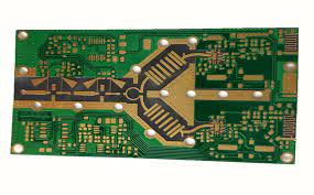
Among all mid-frequency RF substrates, Rogers RO4350B™ stands out as the most balanced, production-friendly laminate that combines low dielectric loss, stable dielectric constant (Dk), high thermal reliability, and excellent manufacturability. This makes RO4350B an ideal material for high-frequency antenna PCBs, RF front-end modules, phased-array beamformers, and microwave subsystems.
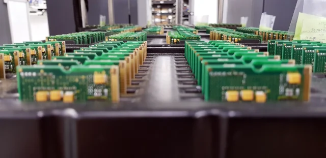
Below, we explore how RO4350B maximizes RF performance and how KKPCB’s high-frequency PCB expertise ensures consistent, low-loss, high-density RF designs for next-generation antenna systems.
1. Why RO4350B Matters: The Foundation of High-Frequency Antenna Performance

In RF engineering, substrate material defines:
-
Insertion loss along RF transmission lines
-
Phase stability across temperature cycles
-
Antenna gain, efficiency, and beam accuracy
-
Power handling for PA (Power Amplifier) and high-current RF networks
-
Impedance control for microstrip/stripline/CPW structures
-
System reliability under high thermal stress
At frequencies from 1 GHz to 40+ GHz, even small shifts in Dk or copper roughness cause:
-
Phase delay errors
-
Beam-steering distortion
-
Increased VSWR
-
Reduced radiation efficiency
This is why RF designers increasingly depend on RO4350B PCB laminates—engineered to deliver consistent high-frequency performance where FR-4 cannot.
2. RF Performance Advantages of RO4350B
(1) High RF Power Handling
RO4350B withstands elevated RF power with:
-
Higher thermal conductivity
-
Low dielectric heating
-
Superior electrical strength
This results in:
-
Higher PA efficiency
-
Stable antenna radiation performance
-
Reduced thermal drift in high-power RF chains
Keyword density: RF power handling / high-power RF / thermal stability / antenna power performance.
(2) Ultra-Stable Dielectric Constant (Dk ≈ 3.48)
RO4350B’s consistent Dk ensures:
-
Precise impedance control
-
Minimal phase distortion
-
Repeatable antenna resonance
-
Accurate phased-array beamforming
Keyword density: Dk stability / dielectric constant / phase stability / RF impedance.
(3) Low Loss Tangent (Df ≈ 0.0037 @10 GHz)
Low-loss RO4350B reduces:
-
Transmission line loss
-
Feed network attenuation
-
RF front-end insertion loss
Ideal for:
-
5G FR1 & FR2 (mmWave)
-
GNSS/L-band
-
Radar 24/77 GHz
-
High-efficiency IoT antennas
Keyword density: low-loss PCB / insertion loss / RF antenna efficiency / microwave PCB.
(4) Excellent Thermal Reliability vs FR-4

FR-4 suffers from:
-
High loss tangent
-
Dielectric drift
-
Poor thermal stability
RO4350B offers:
-
High Tg
-
Low thermal expansion
-
Long-term environmental stability
This makes it suitable for harsh environments:
-
Base-stations
-
Aerospace
-
Automotive radar
-
Outdoor CPE
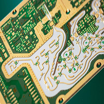
(5) HDI-Ready & High-Density RF Routing
RO4350B supports:
-
Fine-line etching
-
Laser microvias
-
Stacked/buried vias
-
Low-roughness copper
-
High-density RF feed networks
Essential for compact high-frequency antenna modules and beamforming IC integration.
Keyword density: HDI RF PCB / high-density routing / microstrip / CPW / RF module miniaturization.
3. RO4350B vs FR-4 for RF Antenna Applications
| Characteristic | RO4350B | FR-4 |
|---|---|---|
| Df @10 GHz | Ultra-low (~0.0037) | Very high (~0.02) |
| Phase stability | Excellent | Poor |
| Impedance accuracy | ±5% | Inconsistent |
| Thermal reliability | High | Low |
| RF frequency capability | 1–40 GHz | <2 GHz |
| Signal loss | Minimal | Severe |
Summary:
FR-4 cannot maintain stable RF behavior at high frequencies.
RO4350B is the correct choice for low-loss, high-frequency antenna PCBs.
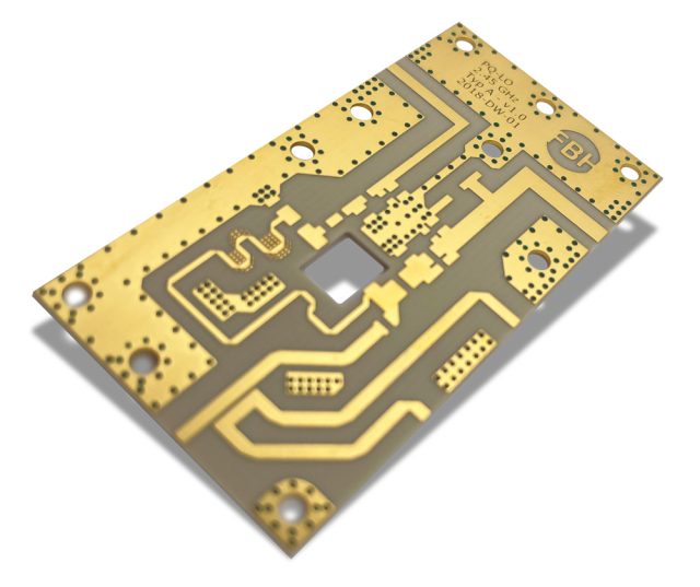
4. Applications Where RO4350B PCB Laminates Excel
-
5G RRU/AAU, small cell, macro cell radio boards
-
Phased-array radar & AESA beamforming modules
-
Automotive 24/77 GHz radar systems
-
Satellite terminals (Ku/Ka bands)
-
High-efficiency IoT & LPWAN antennas
-
Microwave filters, couplers, LNAs, PAs
-
GNSS / GPS antenna front-ends
Every application benefits from low-loss performance, high power handling, and stable phase response.
5. KKPCB’s High-Frequency Manufacturing Capabilities
KKPCB provides advanced manufacturing optimized for RO4350B RF PCBs and hybrid RF stackups, including:
• Impedance Control ±5% for RF Structures
Precise microstrip, stripline, and grounded CPW implementation.
• Advanced Hybrid Stackups (RO4350B + FR-4)
Cost-optimized without compromising RF performance.
• High-Density Interconnect (HDI) RF PCB Manufacturing
Laser microvias, stacked vias, buried vias for compact RF modules.
• Low-Profile Copper for Reduced RF Loss
Lower conductor loss for high-frequency transmission lines.
• Controlled Thermal Pressing for RF Laminates
Prevents voiding and ensures long-term laminate stability.
• Resin-Filled & Capped Vias
Stable RF transitions in antenna feed networks.
• RF Testing & Validation
VNA impedance verification, RF line attenuation measurement.
Keyword density: RF PCB manufacturing / RO4350B PCB fabrication / high-frequency PCB / RF stackup design / KKPCB RF solutions.
6. Conclusion: RO4350B + KKPCB = Superior High-Frequency Antenna Performance
RO4350B PCB laminates deliver:
-
High RF power handling
-
Low-loss high-frequency performance
-
Exceptional phase stability
-
Predictable impedance
-
High-density RF routing capability
Together with KKPCB’s advanced RF PCB manufacturing, HDI capability, and precision impedance control, engineers can build reliable, high-efficiency antenna modules for 5G, radar, satellite, microwave, and high-frequency IoT systems.
If your project requires high-frequency stability, low-loss performance, and high-power RF capability, KKPCB can provide complete stackup engineering, RF optimization, and mass-production support.
