
Taconic TLY-5 PCB differential pairs on a hybrid RF/digital board need a reference-plane strategy that respects both interfaces. The pair may be electrically balanced in isolation yet experience skew or common-mode conversion when it crosses a split, changes layer, or runs beside a phase-sensitive RF path. The project pain is often discovered at system integration, when digital errors and RF noise appear together.
Table of Contents
Define pair geometry on the finished stackup
Use finished dielectric, copper, mask, width, spacing, and reference-plane values. Taconic TLY-5 PCB pair geometry should not be copied from a generic FR-4 rule when the layer construction is different. The RF PCB design PCB design review should record impedance target, skew budget, via transition, and the reference plane used at each segment.
Plan return current at every layer transition
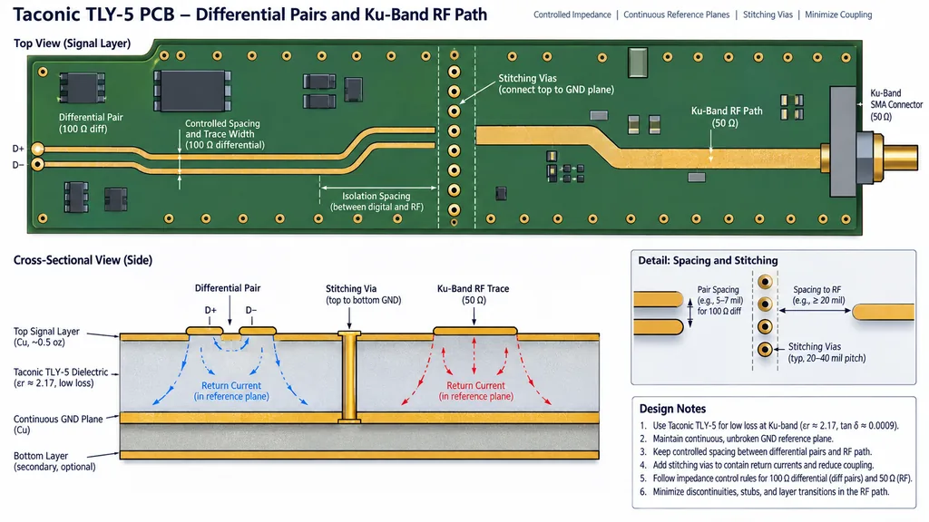
A pair crossing a plane gap can convert differential energy to common mode. Add stitching or a continuous reference transition where the geometry requires it. Taconic TLY-5 PCB via fields should be checked with the RF and digital return map together. The PCB manufacturing controlled-impedance PCB record can identify anti-pad, via pitch, and connector or package escape assumptions.
Keep RF aggressors outside the pair budget
Spacing should reflect rise time, frequency content, parallel run length, and the actual ground structure. Taconic TLY-5 PCB material and finish assumptions should remain stable when the pair is moved for routing. The RF PCB materials high-frequency PCB review can define a no-route corridor, guard trace, or via fence only when those features are manufacturable and inspectable.
Use coupons that reveal conversion, not just impedance
A straight differential coupon verifies only part of the problem. Add a layer transition, reference discontinuity, or connector escape that resembles the product. Taconic TLY-5 PCB coupon geometry should share panel and construction with the board. The controlled-impedance PCB manufacturing package can then compare skew, insertion loss, and cross-section with the design assumptions.
Release mixed-signal acceptance criteria
Freeze pair impedance, skew, return-path continuity, crosstalk target, stackup, and calibration method. Taconic TLY-5 PCB documentation should state calculated targets separately from measured data. The PCB assembly PCB manufacturing and assembly records should identify any rework, connector change, or layer registration shift before system-level debug.
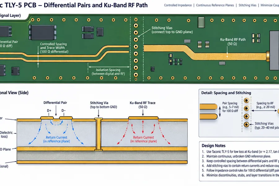
Treat differential pairs as part of the same stackup and return-current map as the RF network. The result is a board that can be debugged by geometry and evidence rather than by guessing which subsystem owns the interference.
Project evidence and handoff for Taconic TLY-5 PCB differential pairs
For hybrid RF and digital routing, record pair impedance, skew allocation, plane crossings, stitching vias, aggressor spacing, connector escape, and coupon construction. That lets system debug begin with a geometry question instead of a subsystem argument. The Taconic TLY-5 PCB drawing should make the critical datum visible to layout, fabrication, assembly, and test. If a number is calculated, retain the assumptions; if it is a supplier typical, keep it labeled as typical; if it is a measured acceptance value, keep the sample, method, and revision traceable.
| Release item | Engineering question | Evidence to retain |
|---|---|---|
| Stackup and material | Does the finished construction match the RF model? | Finished dielectric target, copper assumption, material lot, cross-section |
| Transition or critical path | Is the mechanical datum also the electrical datum? | Launch drawing, via or pad dimensions, mask and connector inspection |
| Process witness | Does the coupon represent the product feature? | Panel position, layer pair, finish, drill and impedance record |
| Assembly and test | Could placement, rework, or calibration move the result? | Placement tolerance, reflow or rework history, fixture and reference plane |
For program control, use a short disposition statement after each build: what passed, what moved, what is still a target, and which owner decides the next change. This keeps the Taconic TLY-5 PCB differential pairs discussion focused on evidence and prevents a new material, finish, or layout change from being introduced without an updated model and acceptance plan.
Sources: Taconic and Rogers typical material data; IPC-TM-650 methods relevant to dielectric, copper, drilling, plating, registration, and impedance; RF application guidance from Qorvo, Analog Devices, and Würth Elektronik; KKPCB PCB design, materials, manufacturing, assembly, and high-frequency capability pages. Values are typical, target, or calculated references unless explicitly identified as measured.
