
Why SiC Technology Is Transforming Power Electronics
As electric vehicles (EVs), renewable energy systems, and industrial automation continue to evolve, traditional silicon-based power devices are increasingly limited in:
- Switching frequency
- Thermal efficiency
- Power density
- High-voltage performance
This has accelerated the adoption of Silicon Carbide (SiC) power electronics, especially in:
- Automotive powertrain systems
- EV inverters
- High-power charging systems
- Industrial motor drives
Compared with traditional silicon devices, SiC MOSFETs and SiC power modules provide:
- Higher switching speed
- Lower switching loss
- Higher operating temperature capability
- Improved power conversion efficiency
However, these advantages also place much higher demands on PCB design, thermal management, EMI suppression, and manufacturing reliability.
At KKPCB, advanced PCB solutions are optimized for high-voltage, high-current, and high-temperature SiC applications.
2. What Is a SiC PCB?
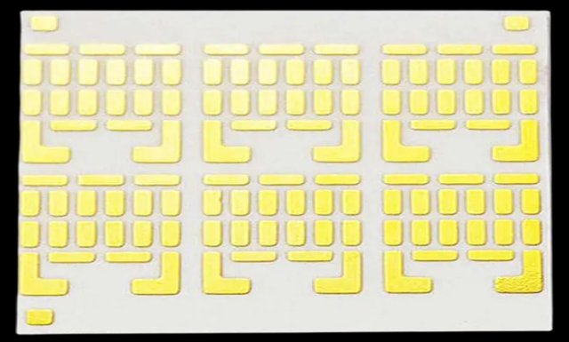
A SiC PCB is a specialized printed circuit board designed to support:
- Silicon Carbide power devices
- High switching frequencies
- High power density applications
These PCBs must withstand:
- High voltage stress
- Large current loads
- Extreme thermal conditions
Typical SiC PCB applications include:
- EV traction inverters
- DC-DC converters
- On-board chargers (OBC)
- Industrial power converters
3. Key Advantages of SiC Power Electronics
3.1 Higher Switching Frequency
SiC devices support much faster switching speeds, enabling:
- Smaller passive components
- Higher power density
- Compact system design
3.2 Reduced Power Loss
Power efficiency is improved due to:
- Lower conduction loss
- Lower switching loss
Power handling is related to:
P=V⋅IP = V \cdot IP=V⋅I
Higher efficiency reduces:
- Heat generation
- Cooling requirements
3.3 High Temperature Operation
SiC devices can operate at significantly higher temperatures than silicon devices, making them ideal for:
- Automotive environments
- Industrial high-power systems
4. PCB Design Challenges for SiC Applications
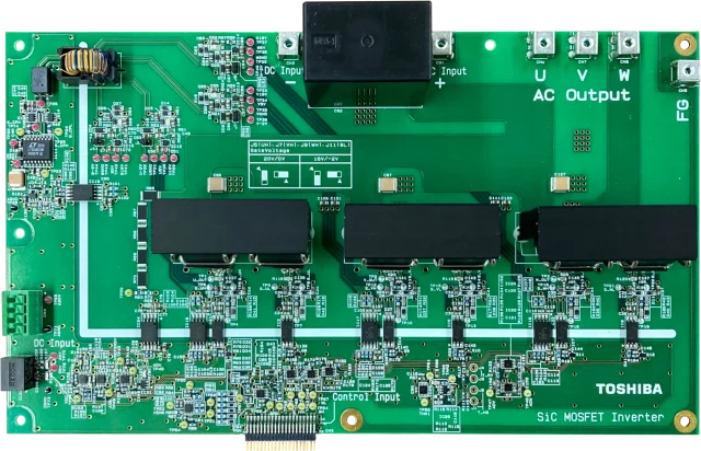
4.1 High dv/dt and di/dt Effects
Fast switching transitions generate:
- Voltage overshoot
- Electromagnetic interference (EMI)
- Signal integrity challenges
4.2 Thermal Management Complexity
High-power SiC modules generate concentrated heat, requiring:
- Efficient heat spreading
- Low thermal resistance design
- Stable long-term thermal reliability
4.3 High-Voltage Isolation Requirements
Automotive powertrain systems require:
- High creepage and clearance distances
- Strong dielectric insulation
- Reliable isolation between power stages and control circuits
5. Thermal Management Strategies for SiC PCB Design
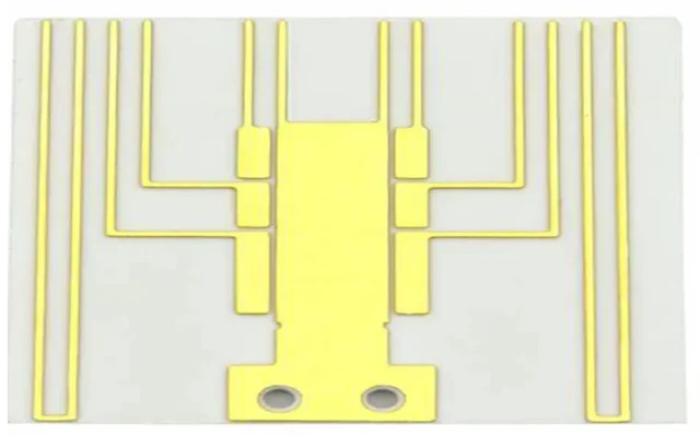
5.1 Heavy Copper PCB Design
To handle high current:
- Thick copper layers (2oz–8oz or higher)
- Wide power traces
- Reinforced copper planes
5.2 Thermal Via Arrays
Thermal vias improve heat transfer from:
- SiC MOSFETs
- Power modules
- High-current switching devices
Benefits include:
- Reduced junction temperature
- Improved reliability
5.3 Metal Core and IMS PCB Solutions
Metal core PCB technologies improve:
- Heat dissipation
- Thermal conductivity
- Mechanical stability
5.4 Heat Sink Integration
Effective thermal systems include:
- Aluminum heat sinks
- Cold plates
- Thermal interface materials (TIM)
6. EMI and Signal Integrity Optimization
6.1 High-Speed Switching Noise
SiC switching edges create strong EMI.
Common issues:
- Ringing
- Crosstalk
- Conducted emissions
6.2 PCB Layout Best Practices
- Minimize switching loop area
- Short gate driver paths
- Separate power and control ground planes
- Use solid grounding structures
6.3 Controlled Impedance Routing
High-speed gate drive signals require stable impedance:
Proper impedance control improves:
- Switching stability
- Signal integrity
- EMI performance
7. PCB Material Selection for SiC Systems
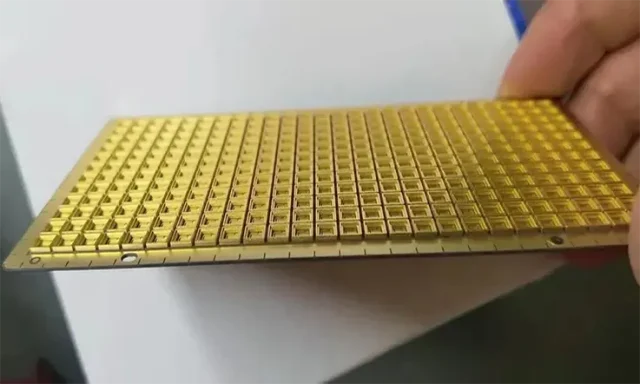
Important material properties:
- High Tg
- High thermal conductivity
- Low dielectric loss
- Strong mechanical reliability
Common PCB materials include:
- High-Tg FR4
- IMS PCB substrates
- Ceramic PCB materials
- Heavy copper laminates
8. Reliability Requirements in Automotive Powertrain Systems
Automotive SiC PCB systems must withstand:
- Thermal cycling
- Mechanical vibration
- High humidity
- Long-term electrical stress
Testing includes:
- Power cycling tests
- Thermal shock tests
- High-voltage insulation testing
At KKPCB, advanced validation processes ensure:
- Long service life
- Stable high-power operation
- Automotive-grade reliability
9. Applications of SiC PCB Technology
SiC PCB solutions are widely used in:
- EV traction inverters
- Fast EV charging stations
- Industrial motor drives
- Renewable energy inverters
- Aerospace power systems
These applications demand:
- High efficiency
- High power density
- Excellent thermal reliability
10. Future Trends in SiC PCB Design
Emerging trends include:
- Higher switching frequencies
- Compact integrated power modules
- Double-sided cooling structures
- Advanced ceramic and hybrid substrates
Future SiC PCB solutions will focus on:
- Improved thermal efficiency
- Lower EMI
- Higher system integration
11. Conclusion
SiC PCB technology is revolutionizing high-power electronics and automotive powertrain systems, enabling:
- Higher efficiency
- Faster switching
- Greater power density
However, achieving reliable performance requires advanced PCB engineering in:
- Thermal management
- High-current routing
- EMI suppression
- High-voltage isolation
With deep expertise in automotive and power electronics manufacturing, KKPCB delivers optimized PCB solutions for next-generation high-power and automotive applications.





