
With electronic products becoming increasingly compact, lightweight, and functionally integrated, traditional rigid PCBs and flexible PCBs are facing new design limitations. Modern applications such as wearable devices, medical equipment, aerospace systems, automotive electronics, and industrial equipment require circuit solutions that can withstand mechanical movement while maintaining high electrical reliability.
Rigid-flex PCB technology combines the advantages of rigid circuit boards and flexible circuits into a single integrated structure. By incorporating flexible PCB layers with rigid PCB sections, rigid-flex boards provide mechanical flexibility, space optimization, and improved reliability compared with traditional PCB assemblies connected by cables or connectors.
This technology has become an important solution for advanced electronic systems where size, weight, reliability, and design freedom are critical factors.
1. What Is a Rigid-Flex PCB?

A rigid-flex PCB is a hybrid circuit board that integrates:
- Rigid PCB sections
- Flexible PCB sections
within one unified board structure.
The rigid sections typically provide:
- Component mounting areas
- Mechanical support
- Structural stability
The flexible sections provide:
- Bending capability
- Three-dimensional installation flexibility
- Reduced connector requirements
Unlike traditional assemblies that use separate rigid PCBs connected by cables, rigid-flex technology creates a continuous electrical connection between rigid and flexible areas.
2. Structure of Rigid-Flex PCBs
A rigid-flex PCB typically consists of multiple layers, including:
- Copper layers
- Polyimide flexible materials
- FR-4 rigid materials
- Adhesive layers
- Coverlay layers
- Protective solder mask layers
The flexible area commonly uses polyimide film because of its:
- Excellent thermal stability
- Mechanical durability
- Chemical resistance
- Flexibility
The rigid area usually uses standard PCB materials such as:
- FR-4
- High-Tg laminates
- Advanced low-loss materials
3. Advantages of Rigid-Flex PCB Technology
3.1 Space Saving and Miniaturization
One of the biggest advantages of rigid-flex PCBs is reduced assembly space.
Traditional designs often require:
- Multiple PCBs
- Cable connections
- Board-to-board connectors
Rigid-flex technology eliminates many of these additional components.
Benefits include:
- Smaller product size
- Reduced assembly complexity
- Improved internal space utilization
This makes rigid-flex PCBs ideal for compact electronic devices.
3.2 Improved Reliability
Connectors and cables are common failure points in electronic assemblies.
Rigid-flex PCBs reduce:
- Connector failures
- Loose connections
- Mechanical stress points
The integrated structure improves reliability under:
- Vibration
- Shock
- Repeated movement
3.3 Three-Dimensional Design Capability
Unlike rigid PCBs, flexible sections can be bent or folded to fit complex mechanical structures.
This enables:
- 3D packaging
- Compact product designs
- More efficient internal layouts
Applications include:
- Wearable devices
- Cameras
- Medical instruments
- Aerospace electronics
3.4 Reduced Weight
By replacing:
- Wire harnesses
- Connectors
- Multiple PCB assemblies
rigid-flex PCBs reduce overall system weight.
This is especially valuable in:
- Aerospace systems
- Portable electronics
- Battery-powered devices
3.5 Better Signal Performance
Removing connectors and cables reduces:
- Signal loss
- Contact resistance
- Electromagnetic interference
Rigid-flex designs can provide more consistent signal transmission, especially for:
- High-speed digital signals
- RF circuits
- Sensor interfaces
4. Rigid-Flex PCB Design Considerations
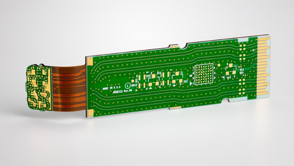
4.1 Material Selection
Material selection directly affects mechanical and electrical performance.
Flexible Materials
Common flexible materials include:
Polyimide
Advantages:
- High temperature resistance
- Excellent dimensional stability
- Long bending life
Rigid Materials
Common rigid materials include:
FR-4
Suitable for:
- General electronic applications
- Industrial control systems
High-Tg materials
Suitable for:
- High-temperature environments
- Automotive and industrial applications
4.2 Flexible Area Bend Requirements
The flexible section must be designed according to bending conditions.
Important factors include:
- Bend radius
- Number of bending cycles
- Copper thickness
- Layer arrangement
General design principles:
- Avoid sharp bends.
- Avoid placing vias directly in bending areas.
- Keep copper traces perpendicular to bending direction when possible.
4.3 Copper Trace Design
Flexible areas experience mechanical stress during bending.
Recommended practices:
- Use curved traces instead of sharp corners.
- Avoid excessive copper density variation.
- Maintain proper spacing between traces.
Curved routing improves mechanical durability by reducing stress concentration.
4.4 Layer Stackup Design
Rigid-flex stackup design requires careful planning.
Important considerations include:
- Transition between rigid and flexible sections
- Layer alignment
- Adhesive thickness
- Copper distribution balance
Poor stackup design may lead to:
- Warpage
- Delamination
- Mechanical failure
4.5 Via Design
Vias require special attention in rigid-flex PCBs.
Recommended practices:
- Avoid placing vias in dynamic bending areas.
- Use appropriate via structures.
- Consider filled vias for high-density areas.
For HDI rigid-flex boards, microvias may be used to improve routing density.
5. Manufacturing Process of Rigid-Flex PCBs
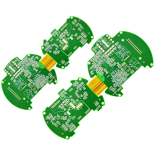
Rigid-flex PCB manufacturing combines flexible PCB fabrication and rigid PCB processing.
Key manufacturing stages include:
Flexible Layer Fabrication
The flexible circuit portion is produced using:
- Polyimide substrate processing
- Copper pattern formation
- Coverlay application
Multilayer Lamination
Rigid and flexible layers are laminated together under controlled conditions.
Critical parameters include:
- Pressure
- Temperature
- Alignment accuracy
Drilling and Plating
Processes include:
- Mechanical drilling
- Laser drilling
- Copper plating
Proper control ensures reliable electrical connections.
Surface Finishing
Common finishes include:
- ENIG
- ENEPIG
- OSP
Selection depends on:
- Component requirements
- Reliability expectations
- Assembly process
6. Applications of Rigid-Flex PCBs
6.1 Medical Electronics
Applications:
- Wearable medical devices
- Diagnostic equipment
- Implantable electronics
Advantages:
- Compact size
- Reliability
- Flexible packaging
6.2 Aerospace and Defense Electronics
Applications:
- Avionics systems
- Navigation equipment
- Communication devices
Requirements:
- Vibration resistance
- Lightweight design
- Long-term reliability
6.3 Automotive Electronics
Applications:
- Advanced driver assistance systems (ADAS)
- Battery management systems
- Sensor modules
Advantages:
- Space optimization
- Mechanical durability
6.4 Consumer Electronics
Applications:
- Smart watches
- Foldable devices
- Cameras
- Mobile products
Requirements:
- Miniaturization
- High integration
6.5 Industrial Equipment
Applications:
- Robotics
- Automation systems
- Control modules
Advantages:
- Resistance to vibration
- Flexible installation
7. Challenges of Rigid-Flex PCB Manufacturing
Higher Manufacturing Complexity
Compared with traditional PCBs, rigid-flex boards require:
- More process control
- More complex lamination
- Advanced manufacturing capability
Higher Cost
Factors increasing cost include:
- Specialized materials
- Additional processing steps
- Lower manufacturing tolerance
However, reduced assembly complexity and improved reliability may offset the initial investment.
Design Complexity
Rigid-flex designs require collaboration between:
- PCB designers
- Mechanical engineers
- Manufacturing engineers
Mechanical and electrical requirements must be considered together.
8. Rigid-Flex PCB Reliability Considerations
For high-reliability applications, engineers should evaluate:
Mechanical Reliability
Including:
- Bend cycle testing
- Flex fatigue testing
- Vibration testing
Electrical Reliability
Including:
- Continuity testing
- Insulation testing
- Signal integrity verification
Environmental Reliability
Including:
- Thermal cycling
- Humidity resistance
- Chemical resistance
9. DFM Considerations for Rigid-Flex PCB Design
Early Design for Manufacturability (DFM) review helps avoid production problems.
Important areas include:
- Flexible area definition
- Bend radius verification
- Material compatibility
- Layer registration
- Component placement
- Assembly process requirements
A manufacturer with rigid-flex experience can provide valuable support during:
- Prototype development
- Engineering validation
- Mass production preparation
Conclusion
Rigid-flex PCB technology represents an important evolution in modern electronic design by combining the structural advantages of rigid boards with the flexibility of flexible circuits.
Its benefits include:
- Reduced size and weight
- Improved reliability
- Better space utilization
- Enhanced design flexibility
- Reduced connector dependency
As electronic products continue moving toward miniaturization, higher integration, and more complex mechanical structures, rigid-flex PCBs will play an increasingly important role in applications such as medical devices, aerospace systems, automotive electronics, industrial automation, and wearable technology.
Successful rigid-flex PCB development requires careful consideration of materials, stackup design, bending requirements, signal integrity, manufacturing capability, and reliability testing to achieve stable performance from prototype to mass production.
