
Printed Circuit Boards (PCBs) are the foundation of modern electronic products, supporting electrical connections between components and enabling complex system functions. However, during development, production, or field operation, PCB failures can occur due to defective components, manufacturing issues, electrical stress, or environmental factors.
Identifying faulty components on a PCB is a critical step in troubleshooting and repair. A systematic fault detection process can help engineers quickly locate failure sources, reduce debugging time, and improve product reliability.
This article explains common PCB component failure symptoms, inspection methods, testing techniques, and best practices for identifying defective components.
Common Causes of PCB Component Failures
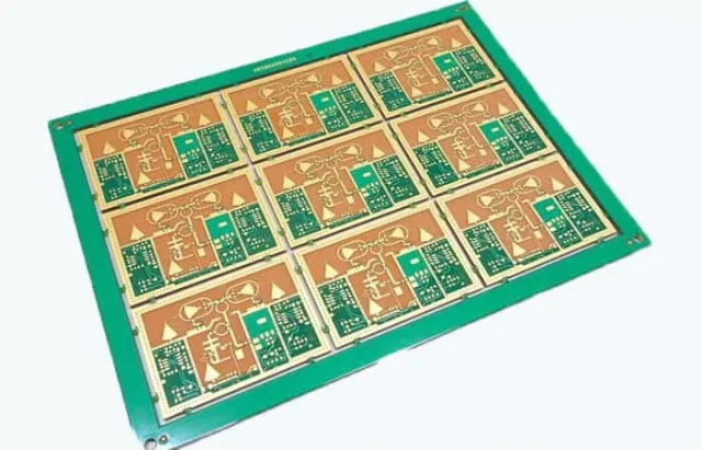
Before locating faulty components, it is important to understand why failures happen. PCB component issues usually come from several sources.
1. Component Quality Issues
Low-quality or damaged components may cause:
- Intermittent operation
- Incorrect voltage output
- Signal instability
- Complete circuit failure
Common causes include:
- Manufacturing defects
- Counterfeit components
- Improper storage conditions
- Component aging
Sensitive components such as ICs, capacitors, and semiconductor devices require strict quality control during sourcing and handling.
2. Electrical Overstress
Excessive electrical stress is one of the most common reasons for component damage.
Typical causes include:
- Overvoltage
- Overcurrent
- Electrostatic discharge (ESD)
- Voltage spikes
For example:
- Capacitors may fail due to excessive voltage stress
- MOSFETs may be damaged by current overload
- ICs may fail due to ESD events
3. Thermal Stress
Heat-related failures can significantly affect PCB reliability.
Common causes include:
- Insufficient thermal management
- High power density
- Poor component selection
- Limited airflow
Signs of thermal damage include:
- Discolored PCB areas
- Burn marks
- Cracked components
- Reduced component lifetime
4. Manufacturing Defects
Some PCB failures originate during assembly.
Typical manufacturing issues include:
- Cold solder joints
- Solder bridges
- Insufficient solder volume
- Component misalignment
- Poor solder wetting
These defects may cause:
- Open circuits
- Short circuits
- Intermittent connections
- Functional failures
Common Signs of Faulty PCB Components
Recognizing failure symptoms can help narrow down the potential problem area.
1. PCB Does Not Power On
Possible causes include:
- Failed power supply components
- Damaged voltage regulators
- Shorted capacitors
- Broken connectors
Recommended checks:
- Measure input voltage
- Inspect power rails
- Check for abnormal resistance
2. Intermittent System Operation
Intermittent failures are often caused by:
- Loose solder joints
- Cracked components
- Aging capacitors
- Thermal expansion effects
These faults may appear only under:
- Temperature changes
- Mechanical vibration
- High operating loads
3. Excessive Heat Generation
Overheating components may indicate:
- Internal short circuits
- Excessive current consumption
- Incorrect component operation
Thermal inspection can help identify abnormal temperature points quickly.
4. Abnormal Signals or Communication Errors
Signal-related failures may result from:
- Damaged ICs
- Incorrect component values
- Poor solder connections
- Signal integrity problems
Common symptoms include:
- Communication failure
- Data errors
- Unstable system behavior
Methods for Finding Faulty Components on PCBs
A combination of visual inspection, electrical testing, and advanced diagnostic tools provides the most effective troubleshooting approach.
1. Visual Inspection
Visual inspection is usually the first step in PCB troubleshooting.
Engineers should check for:
Burn Marks and Physical Damage
Look for:
- Darkened PCB areas
- Melted components
- Cracked packages
- Swollen capacitors
These signs often indicate electrical or thermal failure.
Solder Joint Inspection
Defective solder joints may appear as:
- Cracks
- Voids
- Poor wetting
- Excess solder
Inspection methods include:
- Magnification
- Microscopes
- Automated Optical Inspection (AOI)
Component Placement Verification
Incorrect placement can cause:
- Circuit malfunction
- Reverse polarity issues
- Incorrect operation
Check:
- Component orientation
- Reference designators
- Package types
2. Multimeter Testing
A digital multimeter is one of the most common tools for PCB fault diagnosis.
Continuity Testing
Used to identify:
- Broken traces
- Open circuits
- Unexpected connections
Resistance Measurement
Resistance testing helps detect:
- Short circuits
- Damaged resistors
- Abnormal power rails
For example, an unusually low resistance between power and ground may indicate a shorted component.
Voltage Measurement
Comparing measured voltage with expected values helps locate failures.
Engineers can check:
- Input voltage
- Power rails
- IC supply pins
- Reference voltages
An incorrect voltage reading often points toward the faulty section.
3. Power Consumption Analysis
Current measurement is useful for detecting abnormal components.
A defective component may cause:
- Excessive current draw
- Increased standby power
- Abnormal heating
Common techniques include:
- Measuring total board current
- Comparing with a reference board
- Monitoring power-up behavior
4. Thermal Inspection
Thermal analysis is effective for locating components with abnormal heat generation.
Infrared Thermal Imaging
Thermal cameras can identify:
- Overheating ICs
- Shorted capacitors
- Power component failures
A faulty component often appears as a localized high-temperature area.
Thermal Injection Methods
Engineers may apply controlled power and observe heat distribution.
This method helps locate:
- Hidden shorts
- Power circuit failures
- High-current paths
5. Oscilloscope Testing
Oscilloscopes are essential for analyzing dynamic circuit behavior.
They help verify:
- Clock signals
- Communication waveforms
- PWM signals
- Power ripple
Abnormal waveforms may indicate:
- IC failure
- Incorrect component values
- Signal integrity problems
6. Component-Level Testing
When a suspected component is identified, further testing can confirm the failure.
Capacitor Testing
Check:
- Capacitance value
- Leakage current
- Equivalent Series Resistance (ESR)
Common capacitor failures include:
- Reduced capacitance
- Internal short circuits
- Increased ESR
Resistor Testing
Verify:
- Resistance value
- Physical damage
- Open circuit conditions
Semiconductor Testing
For ICs, diodes, and transistors, engineers can check:
- Junction behavior
- Forward voltage
- Leakage current
- Switching characteristics
Advanced PCB Fault Detection Techniques
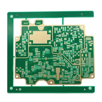
For complex PCB assemblies, advanced inspection methods provide deeper analysis.
X-Ray Inspection
X-ray inspection is useful for detecting hidden defects:
- BGA solder issues
- Internal cracks
- Voids
- Hidden connection failures
It is especially important for high-density PCB assemblies.
Automated Optical Inspection (AOI)
AOI systems detect:
- Missing components
- Wrong components
- Solder defects
- Placement errors
AOI is widely used in PCB manufacturing to improve production quality.
In-Circuit Testing (ICT)
ICT verifies individual circuit nodes and components.
It can test:
- Resistance
- Capacitance
- Component values
- Circuit continuity
ICT helps identify manufacturing-related defects before products reach customers.
Functional Testing (FCT)
Functional testing evaluates whether the PCB performs according to system requirements.
It verifies:
- Real operating conditions
- Communication functions
- Power performance
- Product behavior
Step-by-Step PCB Fault Diagnosis Process
A structured troubleshooting process improves efficiency.
Step 1: Collect Failure Information
Understand:
- Failure symptoms
- Operating conditions
- Failure frequency
- Previous modifications
Step 2: Perform Visual Inspection
Check:
- Physical damage
- Solder quality
- Component condition
Step 3: Verify Power Circuits
Measure:
- Input voltage
- Power rails
- Current consumption
Power-related issues are among the most common PCB failures.
Step 4: Isolate the Fault Area
Divide the circuit into functional blocks:
- Power section
- Control section
- Communication section
- Signal processing section
Testing each block helps narrow the failure location.
Step 5: Test Suspected Components
Use:
- Multimeter
- Oscilloscope
- Thermal camera
- Component analyzer
Step 6: Replace and Validate
After replacing the suspected component:
- Retest electrical performance
- Verify system functions
- Perform reliability validation
How to Prevent PCB Component Failures
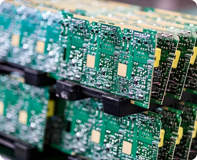
Fault detection is important, but prevention is even more valuable.
Improve Component Selection
Consider:
- Component quality
- Operating temperature range
- Voltage/current ratings
- Supplier reliability
Optimize PCB Design
Important design practices include:
- Proper power distribution
- Thermal management
- Signal integrity control
- Adequate component spacing
Strengthen Manufacturing Quality Control
Recommended processes include:
- AOI inspection
- X-ray inspection
- ICT testing
- Functional testing
Perform DFM Review Before Production
Design for Manufacturing (DFM) analysis helps identify:
- Component placement risks
- Soldering challenges
- Assembly limitations
- Reliability concerns
Early engineering review reduces potential failures before mass production.
Conclusion
Finding faulty components on PCBs requires a combination of observation, measurement, and systematic troubleshooting.
From simple visual inspection and multimeter testing to advanced methods such as thermal imaging, X-ray inspection, and functional testing, engineers can efficiently identify failure sources and improve product reliability.
A reliable PCB is not only determined by component quality but also by:
- Proper circuit design
- Manufacturing control
- Assembly quality
- Comprehensive testing
By applying effective fault diagnosis methods and preventive engineering practices, companies can reduce debugging time, improve production yield, and ensure long-term electronic product performance.
KKPCB provides PCB fabrication, PCBA assembly, DFM analysis, component sourcing, and testing support to help customers identify potential risks and achieve reliable electronic product manufacturing.
