Automotive Radar PCB: The Foundation of Intelligent Mobility | KKPCB
Introduction
Automotive radar technology has become a defining pillar of modern Advanced Driver Assistance Systems (ADAS) and autonomous driving architectures.
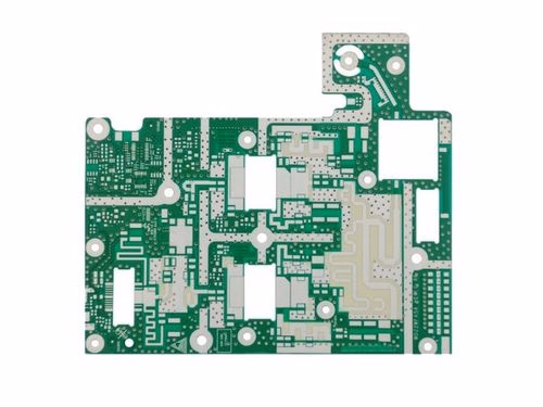
At the core of these radar modules lies an essential enabler of performance — the Automotive Radar PCB.
An Automotive Radar PCB is far more than a carrier of components; it is a precisely engineered electromagnetic platform that governs signal integrity, impedance control, and thermal stability in radar transceiver systems operating across 24 GHz, 77 GHz, and emerging 79–81 GHz frequency bands.
KKPCB specializes in the design and fabrication of high-frequency radar PCBs that meet the stringent demands of automotive reliability, safety compliance, and high-speed data accuracy — ensuring vehicles “see” the world with precision.
The Evolving Role of Automotive Radar Systems
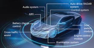
Automotive radar systems enable vehicles to detect and interpret their surroundings through reflected electromagnetic waves. These systems form the sensory foundation for ADAS features such as:
-
Adaptive Cruise Control (ACC)
-
Forward Collision Warning (FCW)
-
Autonomous Emergency Braking (AEB)
-
Blind Spot Detection (BSD)
-
Lane Change Assist (LCA)
-
Cross Traffic Alert (CTA)
The migration from 24 GHz to 77 GHz millimeter-wave radar has revolutionized performance, allowing finer spatial resolution, longer range, and more compact antenna design. Yet, with this evolution, PCB engineering has become the critical determinant of radar accuracy and reliability.
Engineering Challenges in Automotive Radar PCB Design
Radar PCBs differ fundamentally from conventional electronic boards.
At 77 GHz frequencies, even micron-level imperfections can distort signals or generate phase mismatches. Thus, radar PCB design demands RF precision, dielectric stability, and repeatable impedance control.
Key challenges include:
-
Signal Integrity: Ensuring minimal reflection, attenuation, and crosstalk within Tx/Rx channels.
-
Material Performance: Selecting laminates with low dielectric constant (Dk) and loss tangent (Df), such as Rogers RO3003 or PTFE composites.
-
Thermal Management: Mitigating self-heating effects from high-frequency transceivers while maintaining dielectric uniformity.
-
Mechanical Reliability: Achieving dimensional stability under automotive temperature cycles (–40°C to +125°C).
-
EMI Shielding: Preventing electromagnetic interference within densely integrated radar modules.
Advanced PCB Materials for Radar Performance
Material choice directly determines radar signal quality.
Conventional FR-4 substrates fail above 10 GHz due to excessive dielectric losses. KKPCB employs high-frequency laminates such as:
-
Rogers RO3003 / RO4003C: Ideal for 77 GHz applications with Dk ≈ 3.0 ± 0.04 and low loss tangent (~0.002).
-
RT/duroid® 5880: Ultra-low Dk (2.2) and exceptional signal consistency for long-range radar systems.
-
Aluminum Nitride (AlN) Ceramics: Superior thermal conductivity for high-power radar transceivers.
Through precise stackup optimization and copper roughness control, KKPCB achieves stable propagation delay and low insertion loss across the 76–81 GHz band.
PCB Architecture and Routing Strategy
A radar PCB functions as both an electrical pathway and an RF antenna substrate. KKPCB’s engineers implement Grounded Coplanar Waveguide (GCPW) and Microstrip Hybrid Structures to optimize electromagnetic performance.
Design Considerations:
-
Controlled Impedance Routing: Maintains 50Ω ±5% characteristic impedance.
-
Via Stitching: Reduces radiation loss and stabilizes return paths.
-
Short Trace Lengths: Limits phase delay and minimizes insertion loss.
-
Antenna Integration: Incorporates patch or array antennas directly into the radar PCB for compact form factors.
KKPCB uses 3D electromagnetic simulation (HFSS / CST) to validate field distribution, coupling behavior, and S-parameters before fabrication — ensuring designs transition seamlessly from digital model to physical reality.
Reliability and Quality Control in Manufacturing
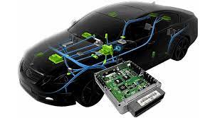
Automotive radar PCBs operate in harsh environments — high vibration, wide temperature swings, and electromagnetic noise.
KKPCB’s manufacturing process incorporates automotive-grade standards and real-time inspection systems to guarantee reliability.
Key quality practices:
-
IPC Class 3 manufacturing precision
-
IATF 16949 and ISO 9001 certified production lines
-
Automated Optical Inspection (AOI) and X-ray defect analysis
-
In-circuit and RF validation testing for every batch
-
Full traceability through serialized PCB identification
Each board is engineered for long-term dielectric consistency, low warpage, and stable signal transmission across millions of operating cycles.
Integration in Modern Automotive Applications
KKPCB’s radar PCBs power a wide spectrum of ADAS and autonomous systems, including:
-
77 GHz long-range front radar for highway driving
-
79 GHz short-range radar for blind-spot monitoring
-
24 GHz corner radar modules for parking assist
-
Hybrid RF + digital radar controllers for sensor fusion platforms
Beyond passenger vehicles, KKPCB’s radar PCB technologies extend to industrial robotics, drones (UAV), and intelligent transportation infrastructure (ITS) — shaping the ecosystem of connected mobility.
Conclusion
Automotive radar PCBs represent the convergence of microwave engineering, material science, and automotive safety.
As vehicles evolve toward autonomy, radar performance increasingly depends on the precision of its underlying PCB.
KKPCB’s deep expertise in RF material selection, signal routing, impedance tuning, and manufacturing control ensures that every radar PCB delivers uncompromising reliability, stability, and accuracy.
KKPCB — Engineering the Intelligence Behind Every Radar Signal.
