
The assembly process is a critical stage in electronic manufacturing, directly affecting product reliability, production efficiency, and overall cost.
Among various PCB assembly methods, Surface Mount Technology (SMT) and Through-Hole Technology (THT) are the two most widely used technologies.
SMT enables high-density component placement and automated mass production, while THT provides strong mechanical reliability and excellent performance for high-stress components.
In modern PCB assembly, these two technologies are not competitors but complementary solutions. Many electronic products use a combination of SMT and THT processes to achieve the best balance between:
- Miniaturization
- Electrical performance
- Mechanical strength
- Manufacturing efficiency
Understanding the advantages and limitations of SMT and THT helps engineers select the most suitable assembly method for different applications.
1. Overview of SMT and THT
1.1 What Is Surface Mount Technology (SMT)?
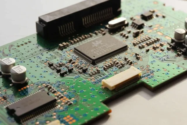
Surface Mount Technology is a PCB assembly method where electronic components are mounted directly onto the surface of the PCB.
Unlike traditional components with long leads, SMT components use small terminals or solder pads to connect with PCB pads.
Common SMT components include:
- Resistors
- Capacitors
- IC packages
- Sensors
- Small connectors
Typical SMT process steps include:
- Solder paste printing
- Component placement
- Reflow soldering
- Inspection and testing
1.2 What Is Through-Hole Technology (THT)?
Through-Hole Technology is a traditional assembly method where component leads pass through drilled holes in the PCB and are soldered on the opposite side.
Common THT components include:
- Large capacitors
- Transformers
- Relays
- Connectors
- Power devices
Typical THT process steps include:
- Component insertion
- Wave soldering or selective soldering
- Inspection
- Testing
2. Advantages of SMT Assembly
2.1 High Component Density
One of the biggest advantages of SMT is its ability to support highly compact PCB designs.
Because SMT components do not require drilled holes:
- More components can be placed on both PCB sides
- Routing space is increased
- PCB size can be reduced
This makes SMT suitable for:
- Smartphones
- Wearable devices
- IoT products
- Compact industrial electronics
2.2 Higher Production Efficiency
SMT assembly is highly automated.
Using:
- Pick-and-place machines
- Automated solder paste printers
- Reflow ovens
manufacturers can achieve:
- Faster production speed
- Consistent assembly quality
- Lower labor requirements
This makes SMT ideal for high-volume production.
2.3 Improved Electrical Performance
SMT components generally have:
- Shorter connection paths
- Lower parasitic inductance
- Reduced signal distortion
Advantages include:
- Better high-frequency performance
- Improved signal integrity
- Reduced electromagnetic interference
SMT is especially suitable for:
- High-speed digital circuits
- RF modules
- Communication devices
2.4 Reduced PCB Size and Weight
Because SMT components are smaller than traditional through-hole components:
- PCB thickness can be reduced
- Product weight can be minimized
This supports the development of:
- Portable electronics
- Miniaturized devices
- Smart wearable products
3. Disadvantages of SMT Assembly
3.1 Lower Mechanical Strength
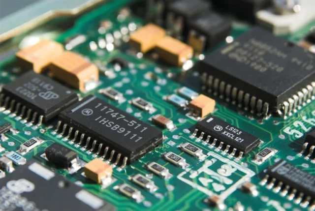
SMT components rely mainly on solder joints for mechanical support.
Compared with THT components, SMT may be more vulnerable to:
- Mechanical shock
- Vibration
- Physical stress
For high-stress environments, additional reinforcement may be required.
3.2 More Sensitive to Manufacturing Accuracy
SMT requires precise control of:
- Component placement
- Solder paste volume
- Reflow temperature profile
Small process deviations may cause:
- Solder bridging
- Component misalignment
- Cold solder joints
3.3 Difficult Manual Repair
Due to:
- Small component size
- Fine-pitch packages
- High-density layouts
SMT repair requires:
- Specialized equipment
- Skilled technicians
4. Advantages of Through-Hole Technology (THT)
4.1 Strong Mechanical Reliability
The biggest advantage of THT is mechanical strength.
Because component leads pass through PCB holes, solder joints provide stronger physical support.
THT is suitable for:
- High vibration environments
- Heavy components
- Industrial equipment
4.2 Better for High-Power Components
THT components are often used in applications requiring:
- High current capability
- Better heat dissipation
- Strong electrical connections
Examples include:
- Power supplies
- Motor controllers
- Industrial control boards
4.3 Easier Inspection and Repair
Compared with SMT:
- Larger component sizes
- Visible solder joints
- Easier replacement
make THT more convenient for:
- Prototype development
- Maintenance applications
- Low-volume production
4.4 Suitable for Large Mechanical Components
Some components cannot easily use SMT packaging.
Examples:
- Large connectors
- Relays
- Transformers
- Electrolytic capacitors
THT provides better structural support.
5. Disadvantages of Through-Hole Technology
5.1 Larger PCB Space Requirement
THT components require:
- Drilled holes
- Additional routing space
This limits PCB miniaturization.
5.2 Lower Assembly Efficiency
Compared with SMT:
- Component placement is slower
- More manual operations may be required
This increases:
- Production time
- Labor cost
5.3 Reduced Routing Flexibility
Through holes occupy PCB space across multiple layers.
Potential issues:
- Reduced routing channels
- More complex multilayer design
5.4 Higher Material Consumption
THT requires:
- More copper area
- Larger PCB footprints
- Additional drilling processes
This may increase manufacturing cost.
6. SMT vs THT Comparison
| Feature | SMT | THT |
|---|---|---|
| Component Size | Smaller | Larger |
| Assembly Speed | High | Lower |
| Automation Level | High | Medium |
| Mechanical Strength | Moderate | Excellent |
| High-Density Design | Excellent | Limited |
| Repair Difficulty | Higher | Easier |
| High-Power Application | Limited | Suitable |
| Production Volume | Mass production | Small to medium production |
| PCB Space Usage | Low | Higher |
7. SMT and THT Hybrid Assembly
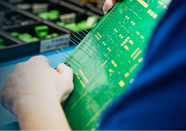
In modern PCB manufacturing, many products use a combination of SMT and THT.
A typical hybrid assembly process includes:
Step 1: SMT Assembly
Components are placed using:
- Solder paste printing
- Pick-and-place machines
- Reflow soldering
Step 2: THT Assembly
Through-hole components are installed using:
- Manual insertion
- Automatic insertion
- Wave soldering
- Selective soldering
Step 3: Inspection and Testing
Final quality verification may include:
- AOI inspection
- X-ray inspection
- Functional testing
- Electrical testing
8. Application Examples
SMT Applications
Common fields include:
Consumer Electronics
Examples:
- Smartphones
- Tablets
- Wearable devices
Requirements:
- Small size
- High integration
Communication Equipment
Examples:
- Wireless modules
- Network devices
Requirements:
- High-speed signal performance
Medical Electronics
Examples:
- Portable monitoring devices
Requirements:
- Compact and reliable design
THT Applications
Common fields include:
Industrial Electronics
Examples:
- Industrial controllers
- Automation equipment
Requirements:
- Mechanical reliability
Power Electronics
Examples:
- Power converters
- Motor control systems
Requirements:
- High current capability
- Thermal performance
Transportation Electronics
Examples:
- Vehicle control systems
Requirements:
- Vibration resistance
- Long-term durability
9. How to Choose Between SMT and THT?
The choice depends on product requirements.
Choose SMT When:
- Miniaturization is important
- Production volume is high
- High-speed performance is required
- Component density is high
Choose THT When:
- Mechanical strength is critical
- Components are large or heavy
- High current handling is required
- Easy maintenance is needed
Choose Hybrid Assembly When:
- The product requires both compact design and mechanical reliability
Examples:
- Industrial control boards
- Power management systems
- Automotive electronics
10. Manufacturing Considerations
Regardless of assembly method, successful PCB production requires consideration of:
DFM (Design for Manufacturing)
Engineers should evaluate:
- Component spacing
- Solderability
- Assembly sequence
- Testing requirements
Component Availability
Selection should consider:
- Supply chain stability
- Lifecycle management
- Alternative components
Testing Requirements
Appropriate testing methods include:
- AOI
- ICT
- Functional testing
- X-ray inspection
Conclusion
SMT and Through-Hole Technology each have unique advantages and limitations.
SMT provides:
- High-density integration
- Fast automated production
- Excellent electrical performance
THT provides:
- Strong mechanical reliability
- Better support for large and high-power components
In modern PCB assembly, the best solution is often a combination of both technologies. By selecting the appropriate assembly method based on product requirements, engineers can achieve the optimal balance between performance, reliability, and manufacturing efficiency.
