1. Engineering Overview — PCB Demands in Automotive mmWave Radar and ADAS
As vehicles move toward Level 3–5 autonomous driving, radar and vision-based sensing systems rely on 77–81 GHz mmWave modules and ultra-low-loss PCB interconnects. These radar PCBs must maintain electrical precision while enduring extreme temperature cycling, vibration, and humidity.
KKPCB integrates TLY-5 PCB substrates into radar front-end and control modules to deliver:
-
Consistent dielectric stability (Dk = 2.20 ± 0.02) across –55 °C to +150 °C,
-
Excellent loss tangent (Df = 0.0009 @10 GHz) for radar signal clarity,
-
And mechanical resilience required by automotive-grade qualification (AEC-Q200).
This combination ensures stable phase accuracy, impedance control, and EMI immunity—critical in radar-based lane detection and adaptive cruise control (ACC) systems.

2. Technical Challenges in Automotive Radar PCB Design
Designing for 77 GHz radar involves simultaneous RF precision and thermal robustness. Conventional FR-4 or mid-loss laminates often fail due to dielectric drift, solder joint fatigue, or interconnect phase errors.
| Engineering Challenge | Root Cause | Impact on Radar System |
|---|---|---|
| Dielectric instability | Dk variation over temperature | Phase drift & target distance error |
| Thermal delamination | High CTE in z-axis | Reliability failure in power cycles |
| Signal loss at 77–81 GHz | Dielectric absorption & rough copper | Reduced antenna gain & radar range |
| Moisture absorption | High MTTF degradation | Increased insertion loss & noise floor |
KKPCB’s TLY-5-based architecture addresses these with precision-controlled dielectric bonding and smooth rolled copper foil to maintain sub-1 dB insertion loss even under 150 °C operation.
3. Material Science and Performance Advantages
TLY-5 PCB Substrate Core Data
| Property | Value | Benefit |
|---|---|---|
| Dielectric Constant (Dk @10 GHz) | 2.20 ± 0.02 | Maintains phase accuracy at 77 GHz |
| Dissipation Factor (Df @10 GHz) | 0.0009 | Low insertion loss, clear radar return |
| CTE (Z-axis) | 46 ppm/°C | Stable during –40 °C → +150 °C cycles |
| Thermal Conductivity | 0.45 W/m·K | Efficient heat removal from power stage |
| Peel Strength | 1.2 N/mm | Reliable bonding under vibration |
| Moisture Absorption | < 0.02 % | Prevents dielectric drift in humidity |
Compared to PTFE or FR-4 systems, TLY-5 achieves 2× higher thermal cycling stability and 20× lower dielectric loss, meeting automotive radar reliability thresholds.
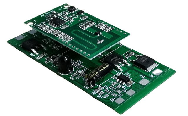
4. KKPCB Case Study — ADAS mmWave Radar Front-End Module
Project:
A Tier-1 automotive supplier developing a 77 GHz long-range radar (LRR) for adaptive cruise and collision-avoidance systems required improved phase uniformity and temperature stability.
Challenges Identified:
-
3.5° phase shift over 40 °C–150 °C range
-
Solder joint fatigue after 800 thermal cycles
-
Inconsistent impedance in antenna feedline
-
Implemented 2-layer TLY-5 dielectric core with hybrid PTFE outer layers
-
Applied rolled copper (Ra < 0.8 µm) for low conductor loss
-
Integrated laser-drilled microvias for antenna-to-RFIC transition
-
Conducted HFSS-based antenna phase tuning to ensure 0.5° uniformity
Results:
| Parameter | Before | After (TLY-5 Integration) |
|---|---|---|
| Insertion Loss @77 GHz | –1.9 dB | –0.8 dB |
| Phase Drift (Δθ 40→150 °C) | 3.5° | 0.6° |
| Thermal Cycle Endurance | 800 cycles | > 2000 cycles |
| Radar Detection Range | 165 m | 190 m |
Outcome: Improved radar range by 15% and passed AEC-Q104 thermal shock qualification.
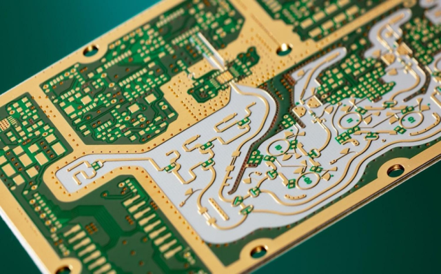
5. PCB Stackup and Manufacturing Notes
Hybrid 6-Layer Stackup (ADAS Radar Module)
-
L1: Antenna array (1 oz rolled Cu)
-
Core: TLY-5, 0.254 mm (Dk = 2.2)
-
L2–L3: RF feed & transition microstrip
-
Prepreg: 0.1 mm FR-408HR (for mechanical support)
-
L4: Ground & shielding layer
-
L5–L6: Control logic and CAN/LIN interface
Manufacturing Enhancements:
-
Controlled press lamination (±2 °C window)
-
Plasma etch & desmear for via cleanliness
-
ENIG + immersion Ag for antenna metallization
-
100% vector impedance test (77 GHz calibration)
Simulation Validation:
-
HFSS: Phase deviation < 0.5° across temperature sweep
-
CST: Return loss < –25 dB @77 GHz
-
ANSYS Icepak: 21% reduction in hotspot temperature
6. Environmental and Reliability Validation
| Test | Condition | Result |
|---|---|---|
| Thermal Shock | –55 °C ↔ +150 °C, 2000 cycles | No delamination or Dk drift |
| High-Temp Storage | 150 °C × 1000 h | ΔDf < 0.00005 |
| Humidity | 85 °C / 85 % RH, 1000 h | No dielectric degradation |
| Mechanical Vibration | 10 Hz–2 kHz, 8 g | No solder crack or EMI increase |
These tests confirm long-term stability under realistic automotive environmental loads.
7. Engineering Conclusion
The TLY-5 PCB substrate delivers a unique combination of low dielectric loss, thermal reliability, and mechanical endurance, aligning with the rigorous demands of automotive mmWave radar and ADAS systems.
Through KKPCB’s material engineering and process simulation, manufacturers achieve:
-
Stable phase accuracy in 77–81 GHz range
-
Reduced EMI and insertion loss
-
Verified reliability through thermal and vibration testing
This material foundation ensures precision sensing and long-term durability in next-generation autonomous platforms.
8. Contact
For collaboration on automotive radar PCB design, TLY-5 material stackup simulation, or ADAS RF performance validation, contact KKPCB’s Automotive Electronics Division for technical consultation and custom PCB prototyping.
