1. KKPCB Rogers RO3003 Introduction
- Rogers RO3003 is a high-frequency PCB laminate engineered for applications demanding stable electrical performance, low loss, and excellent thermal reliability.
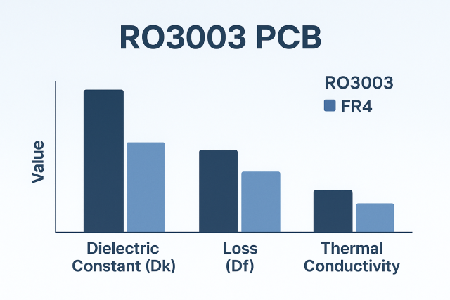
It belongs to the Rogers RO3000™ Series, widely used in automotive radar, 5G modules, satellite communication, and RF front-end systems. - Unlike conventional FR4, which shows high dielectric variation and loss at microwave frequencies, RO3003 uses a ceramic-filled PTFE composite that maintains its dielectric properties even at 24GHz–77GHz and under wide temperature swings.
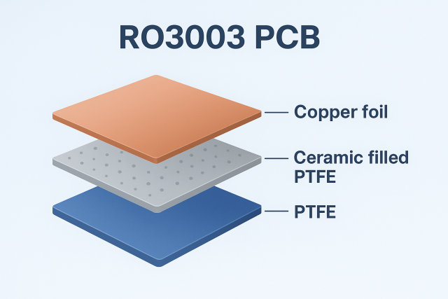
2. Material Composition and Structure
- RO3003 is built on a PTFE (polytetrafluoroethylene) resin system filled with ceramic micro-particles.
This structure provides both mechanical stability and tight dielectric constant control, critical for precision RF designs.
| Parameter | Typical Value | Description |
|---|---|---|
| Dielectric Constant (Dk) | 3.00 ± 0.04 | Stable from 8GHz to 77GHz |
| Dissipation Factor (Df) | 0.0010 @ 10GHz | Extremely low insertion loss |
| Thermal Conductivity | 0.50 W/m·K | Efficient heat dissipation |
| CTE (X/Y/Z) | 17 / 17 / 24 ppm/°C | Excellent dimensional control |
| Moisture Absorption | 0.04% | Resistant to high humidity |
| Glass Transition (Tg) | >280°C | Stable under reflow temperature |
3. Electrical and RF Performance
- RO3003 shows outstanding electrical consistency across frequencies and temperatures.
Its low dielectric loss and constant Dk make it one of the most trusted materials for RF circuit designers.
(1)Low Dielectric Loss
- With a Df of 0.0010, RO3003 minimizes signal attenuation, allowing cleaner transmission at high data rates and microwave frequencies.
(2)Stable Dk Across Frequency
- The dielectric constant remains almost flat over a wide range, ensuring accurate impedance control and phase stability.
(3)Excellent Impedance Repeatability
- Ideal for microstrip, stripline, and coplanar waveguide structures used in 5G or radar modules.
(4)Thermal Compatibility
- The low CTE in all directions ensures dimensional alignment between copper and substrate during thermal cycling and reflow soldering.
4. Design Considerations for RO3003 PCBs
Designing with RO3003 requires both electrical simulation accuracy and process expertise.
(1) Copper Foil Selection
-
Use rolled or reverse-treated copper (RTF) to enhance adhesion and minimize conductor surface roughness.
-
Smoother copper leads to lower insertion loss.
(2) Lamination Process
-
Vacuum lamination is recommended with strict temperature control (~290°C).
-
Avoid excessive pressure to prevent resin squeeze-out.
-
Proper cooling prevents warpage and resin voids.
(3) Drilling and Plating
-
PTFE-based materials are soft; plasma etching or sodium etching improves hole-wall adhesion.
-
Maintain drill bit sharpness and lower spindle speed to avoid delamination.
(4) Impedance Modeling
-
Use tools like Polar SI8000 or ADS LineCalc for precise stack-up simulation.
-
Fine-tune trace width and spacing to achieve ±5% impedance tolerance.
5. Typical Applications
RO3003 PCB are widely adopted in industries that demand signal precision and environmental reliability.
-
Automotive Radar (76–81GHz)
Used in adaptive cruise control and collision avoidance systems. -
5G mmWave Antenna Modules
Enables high-speed, low-loss communication in compact RF systems. -
Satellite and Aerospace Communication
Provides phase stability and low loss for microwave transmitters. -
RF Power Amplifiers and Filters
Ensures low intermodulation distortion and reliable impedance matching.
6. Summary
- Rogers RO3003 PCB offers an ideal combination of low loss, stable dielectric performance, and mechanical robustness, making it a preferred choice for engineers designing next-generation RF and microwave systems.
- For designers and sourcing teams focusing on precision impedance control, signal integrity, and material reliability, RO3003 stands as one of the most proven and consistent laminates available in the high-frequency domain.
