
Why PCB Manufacturing Precision Matters at Millimeter-Wave Frequencies
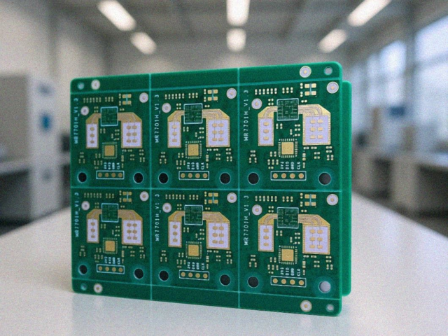
Millimeter-wave applications such as 77GHz automotive radar, 5G mmWave communication, satellite systems, and advanced RF modules require extremely high levels of electrical accuracy.
At these frequencies, PCB performance is no longer determined only by material selection and circuit design. Manufacturing variations that may be insignificant at lower frequencies can create measurable impacts on:
- Insertion loss
- Phase response
- Impedance stability
- Signal propagation accuracy
Due to the extremely short wavelengths of millimeter-wave signals, parameters such as:
- Copper thickness variation
- Surface finish selection
- Conductor geometry
- Copper roughness
- Etching precision
can directly influence RF performance.
Therefore, achieving reliable millimeter-wave PCB performance requires close control of both PCB materials and manufacturing processes.
Copper Thickness Control: Impact on Millimeter-Wave Signal Performance
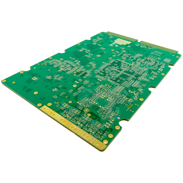
Why Copper Thickness Variation Matters
In millimeter-wave PCB fabrication, copper thickness is a critical factor affecting transmission line characteristics.
During PCB manufacturing, copper thickness variation may occur due to:
- Original copper foil tolerance
- Electroplating variation
- Panel position effects during plating
- Manufacturing process differences
Typically, plated copper tends to be thinner in the center area of a production panel and thicker near the edges. These variations can affect RF consistency between different boards produced in the same batch.
At frequencies above tens of GHz, copper thickness variation may influence:
- Effective dielectric constant (Dk)
- Insertion loss
- Phase response
- Coupling characteristics
This is especially important for:
- Grounded coplanar waveguide (GCPW)
- Coupled transmission lines
- Phase-sensitive RF circuits
Copper Thickness Effects on Different Transmission Line Structures
Microstrip Transmission Lines
Compared with coupled structures, microstrip circuits are generally less sensitive to copper thickness variation.
A thicker copper conductor may slightly reduce insertion loss because:
- More electromagnetic energy exists in the air region
- Wider conductor surfaces reduce conductor loss
However, excessive copper thickness may introduce higher-order mode effects at millimeter-wave frequencies.
Grounded Coplanar Waveguide (GCPW)
GCPW structures are more sensitive to copper thickness changes.
Copper thickness affects:
- Electric field distribution
- Coupling characteristics
- Effective Dk
- Phase consistency
Thicker conductors create different field distributions and can change the transmission behavior of tightly coupled RF structures.
For applications such as:
- 77GHz radar sensors
- Beamforming networks
- 5G phased-array systems
phase stability becomes a critical design consideration.
Surface Finish Selection for Millimeter-Wave PCBs
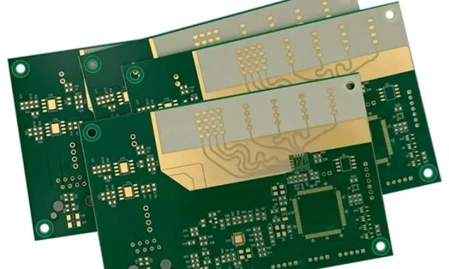
Why Surface Finish Affects RF Performance
Traditional PCB surface finishes are selected mainly for:
- Solderability
- Corrosion protection
- Assembly reliability
However, at millimeter-wave frequencies, surface finish also affects:
- Conductor loss
- Insertion loss
- Phase response
Because RF current flows primarily near the conductor surface (skin effect), the conductivity and thickness of surface coatings become increasingly important.
ENIG vs Low-Loss Surface Finishes
Limitations of ENIG for Millimeter-Wave Applications
Although ENIG is widely used in PCB manufacturing, its nickel layer can introduce additional RF loss.
At high frequencies:
- Nickel has higher resistivity than copper
- Thickness variation affects current distribution
- Phase response may shift
For millimeter-wave circuits requiring high phase accuracy, ENIG may introduce unacceptable performance variation.
Alternative Surface Finishes
For high-frequency and millimeter-wave PCBs, manufacturers often consider:
Immersion Silver (ImAg)
Advantages:
- Low RF loss
- Good conductivity
- Suitable for high-frequency transmission lines
Immersion Tin (ImSn)
Advantages:
- Thin coating thickness
- Lower impact on phase variation compared with ENIG
OSP
Advantages:
- Low insertion loss
- Suitable for selected RF applications
Selecting the correct surface finish is essential for maintaining signal integrity in mmWave circuits.
Conductor Geometry and Etching Precision
The Importance of Conductor Shape
At millimeter-wave frequencies, PCB traces must maintain precise geometry.
An ideal RF conductor should have:
- Straight sidewalls
- Consistent width
- Accurate spacing
However, manufacturing processes may create trapezoidal conductor profiles due to:
- Copper plating thickness
- Etching conditions
- Over-etching
- Copper burr formation
These geometric variations can change electromagnetic field distribution and affect effective Dk and phase response.
Copper Roughness and Signal Loss
Copper surface roughness also influences millimeter-wave performance.
Higher copper roughness increases:
- Conductor loss
- Insertion loss
- Phase variation
At high frequencies, even small variations in copper foil roughness can affect RF consistency between circuits.
Therefore, low-profile copper foil and controlled copper treatment are preferred for:
- 5G mmWave modules
- Automotive radar PCB
- High-frequency test boards
Solder Mask Considerations in Millimeter-Wave PCB Design
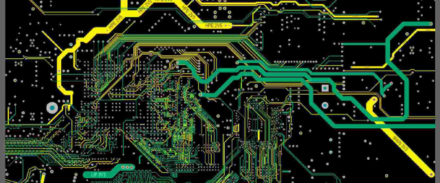
Traditional solder mask materials can influence electromagnetic fields around RF traces.
For microstrip and GCPW structures, solder mask may:
- Change effective dielectric properties
- Increase insertion loss
- Affect phase response
At higher frequencies, unnecessary solder mask coverage around RF transmission lines should be minimized.
KKPCB Manufacturing Solutions for Millimeter-Wave PCBs
To support advanced RF applications, KKPCB focuses on controlling key manufacturing variables that influence millimeter-wave performance.
Manufacturing Capabilities Include:
Precision RF PCB Fabrication
- Controlled copper thickness
- Low-profile copper processing
- Fine-line circuit fabrication
- High-accuracy layer registration
High-Frequency Process Control
- Controlled impedance manufacturing
- TDR verification
- RF material processing
- Surface finish optimization
Application Support
- 77GHz automotive radar PCB
- 5G mmWave PCB
- RF antenna modules
- Microwave test boards
- High-frequency communication systems
Through optimized fabrication processes and engineering collaboration, KKPCB helps customers achieve stable RF performance from prototype development to volume production.
Conclusion: Manufacturing Precision Defines Millimeter-Wave PCB Reliability
At millimeter-wave frequencies, PCB manufacturing variation can directly influence electrical performance.
Factors including:
- Copper thickness
- Surface finish
- Trace geometry
- Copper roughness
- Solder mask design
must be carefully controlled to achieve stable:
- Insertion loss
- Phase response
- Impedance performance
For advanced RF applications such as 77GHz radar, 5G mmWave communication, and high-frequency sensing systems, selecting an experienced millimeter-wave PCB manufacturing partner is essential for achieving reliable and repeatable performance.
