
With the rapid development of industrial automation, intelligent manufacturing, and energy-efficient control systems, accurate current monitoring has become increasingly important for modern industrial equipment.
Magnetic current sensors provide a non-invasive method for measuring electrical current by detecting the magnetic field generated around a conductor. Compared with traditional current sensing methods, they offer advantages such as:
- Electrical isolation between primary and secondary circuits
- Fast response speed
- Low power consumption
- High reliability
- Compact integration capability
However, achieving stable current measurement in industrial environments requires more than selecting a suitable sensor component. The supporting PCBA (Printed Circuit Board Assembly) must address challenges including:
- Signal accuracy
- Noise interference
- Power stability
- Thermal reliability
- Manufacturing consistency
This case study presents how KKPCB supported an industrial automation project through a customized magnetic current sensor PCBA solution, improving measurement reliability, system integration, and production readiness.
1. Project Background
A customer developing an industrial automation control system required a compact current monitoring module for integration into motor control and power management equipment.
The current sensor module was designed to monitor electrical parameters in real time and provide feedback to the control system for:
- Equipment protection
- Energy management
- Control optimization
The product requirements included:
- High measurement accuracy
- Fast current response
- Electrical isolation capability
- Compact PCB size
- Stable operation in industrial environments
During prototype evaluation, the customer identified several PCB-level challenges related to signal stability, electromagnetic interference, and production optimization.
2. Key Challenges in Magnetic Current Sensor PCBA Development
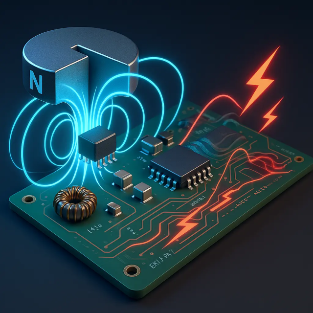
Challenge 1: Current Measurement Accuracy and Signal Stability
Customer Pain Point
Magnetic current sensors are sensitive to external interference and PCB layout conditions.
Potential issues included:
- Measurement deviation
- Signal noise
- Offset fluctuation
- Temperature-related drift
Factors affecting accuracy included:
- Sensor placement
- Signal routing
- Grounding design
- Power supply stability
The PCBA required careful optimization to maintain reliable measurement results.
Challenge 2: EMI/EMC Interference in Industrial Environments
Customer Pain Point
Industrial automation systems often contain strong electromagnetic interference sources, such as:
- Motors
- Inverters
- Switching power supplies
- High-current cables
These sources may affect weak sensor signals and cause:
- Incorrect current readings
- Communication instability
- Control system errors
The PCB design needed improved:
- Noise isolation
- Signal shielding
- Grounding strategy
Challenge 3: Integration of Sensor, Control, and Communication Circuits
Customer Pain Point
The compact sensor module required integration of multiple functional blocks:
- Magnetic sensing circuit
- Signal conditioning circuit
- MCU control unit
- Communication interface
- Power management circuit
Limited PCB space created challenges in:
- Component placement
- Signal separation
- Thermal distribution
- Assembly feasibility
Challenge 4: Power Supply Stability
Customer Pain Point
The sensor module required stable low-voltage power operation.
Power fluctuations could influence:
- Sensor output accuracy
- Signal processing performance
- Communication reliability
The PCBA required optimized:
- Power filtering
- Voltage regulation
- Protection circuits
Challenge 5: Transition from Prototype to Mass Production
Customer Pain Point
The prototype achieved basic functionality, but production required improvements in:
- Manufacturing consistency
- Assembly reliability
- Testing efficiency
Potential risks included:
- Fine-pitch component assembly
- Soldering defects
- Limited test accessibility
3. KKPCB Engineering Support and Solutions
3.1 PCB Design Review and DFM Optimization
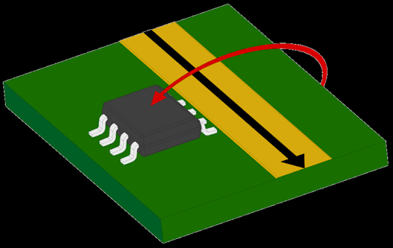
Before production, KKPCB engineering team conducted a comprehensive review focusing on:
- PCB layout structure
- Component placement
- Manufacturing feasibility
- Testing requirements
Optimization actions included:
- Improving component arrangement
- Enhancing assembly accessibility
- Adding test points
- Reducing production risks
This helped the customer achieve a smoother transition from prototype validation to production.
3.2 Signal Integrity and Noise Reduction Optimization
To improve magnetic current measurement stability, PCB layout optimization focused on:
Signal Path Optimization
The engineering team improved:
- Sensor output routing
- Signal trace length
- Sensitive signal separation
This reduced:
- Noise coupling
- Signal distortion
- Measurement fluctuations
Grounding Strategy Improvement
Optimization included:
- Improved ground return paths
- Reduced interference between functional areas
- Better separation between power and sensing circuits
3.3 Power Management Optimization
The PCBA power section was optimized through:
- Voltage regulation improvement
- Filtering circuit optimization
- Noise reduction design
The improvements helped provide:
- More stable sensor operation
- Better measurement consistency
- Improved system reliability
3.4 Communication Interface Optimization
For industrial communication functions, KKPCB optimized:
- Interface protection circuits
- Signal routing
- EMC performance
The solution supported reliable communication between:
- Current sensor module
- Industrial controller
- Monitoring system
3.5 Thermal and Reliability Optimization
Although magnetic current sensors generally have low power consumption, industrial applications require long-term stability.
The design considered:
- Component heat distribution
- PCB copper area
- Operating environment
- Material reliability
These improvements enhanced:
- Operating lifetime
- Environmental adaptability
- Product consistency
4. Manufacturing and Quality Control Process
PCB Fabrication
The customized current sensor PCBA required attention to:
- Multilayer PCB structure
- Signal isolation
- Surface finish quality
- Dimensional accuracy
Material selection considered:
- Electrical performance
- Thermal stability
- Industrial reliability
SMT Assembly
The assembly process included:
Solder Paste Printing
Ensuring:
- Accurate solder volume
- Reliable fine-pitch assembly
Automated Component Placement
High-precision placement was used for:
- Sensor interface components
- IC devices
- Passive components
Reflow Soldering
Optimized profiles ensured:
- Stable solder joints
- Reduced thermal stress
Inspection and Testing
Quality control included:
SPI Inspection
Checking:
- Solder paste printing accuracy
AOI Inspection
Detecting:
- Missing components
- Placement errors
- Solder defects
Functional Testing
Validation included:
- Current measurement accuracy
- Signal output stability
- Communication performance
- Power consumption
5. PCB Technologies Used for Magnetic Current Sensor Applications
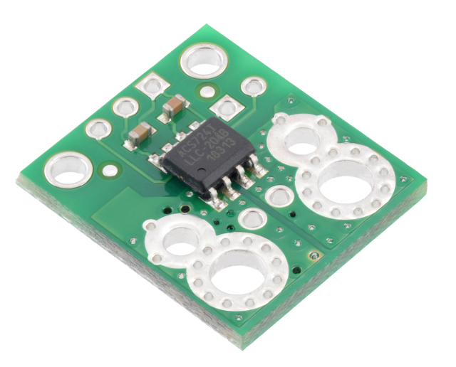
5.1 Multilayer PCB
Advantages:
- Better signal separation
- Improved power distribution
- Higher integration capability
Applications:
- Industrial monitoring modules
5.2 High-Tg FR-4 PCB
Advantages:
- Better thermal stability
- Improved reliability under temperature variation
Applications:
- Industrial control equipment
5.3 HDI PCB
Advantages:
- Compact size
- Higher routing density
Applications:
- Miniaturized sensor modules
6. Applications of Magnetic Current Sensor PCBAs
Industrial Motor Control
Applications:
- Servo drives
- Motor controllers
- Automation equipment
Functions:
- Current monitoring
- Overcurrent protection
- Performance optimization
Power Management Systems
Applications:
- Industrial power supplies
- Energy monitoring equipment
Functions:
- Real-time current measurement
- Power efficiency analysis
Renewable Energy Equipment
Applications:
- Solar inverters
- Energy storage systems
Functions:
- Current feedback
- System protection
Electric Mobility Systems
Applications:
- Charging equipment
- Motor control modules
Functions:
- Battery current monitoring
- Power management
7. Project Results
Through PCB design optimization, signal improvement, and manufacturing process control, the project achieved:
- Improved current measurement stability
- Enhanced EMI resistance
- Better production consistency
- Reduced prototype-to-production risks
Validation results included:
- 98%+ first-pass production yield
- Improved signal repeatability during operation
- Reduced debugging time during system integration
8. Key Engineering Insights
8.1 Sensor Accuracy Depends on PCB-Level Design
A high-performance magnetic sensor requires not only a quality sensing element but also optimized:
- PCB layout
- Power design
- Signal routing
- Noise control
8.2 Industrial Sensor PCBAs Require Strong EMC Capability
Industrial environments introduce complex electrical interference.
Reliable designs should consider:
- Grounding
- Filtering
- Isolation
- Signal integrity
from the beginning of development.
8.3 Early DFM Review Improves Production Reliability
Prototype success does not always guarantee stable mass production.
Early engineering review helps identify:
- Assembly issues
- Testing challenges
- Reliability risks
before production scaling.
Conclusion
Magnetic current sensor PCBAs play an important role in modern industrial automation systems by providing accurate electrical monitoring and feedback control.
A reliable solution requires comprehensive consideration of:
- Measurement accuracy
- Signal integrity
- EMI/EMC performance
- Power stability
- Manufacturing feasibility
In this project, KKPCB supported the customer through PCB design optimization, signal integrity improvement, EMC enhancement, and production process control, helping transform a magnetic current sensing concept into a reliable industrial automation solution.
As industrial systems continue moving toward smarter and more efficient operation, customized PCBA solutions will remain essential for enabling accurate sensing, intelligent control, and reliable equipment performance.
