
This Rogers vs FR4 guide compares the two material families on the properties that drive high-frequency performance and manufacturability, and explains when a high-frequency PCB really needs a Rogers material.
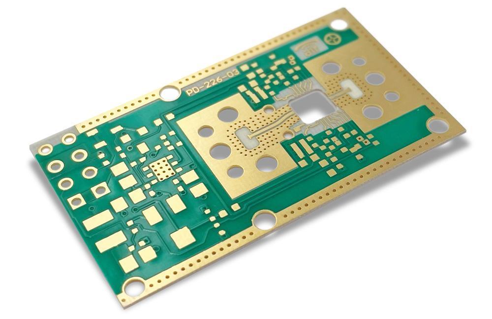
1. Rogers vs FR4: What Is the Difference?
FR-4 is a class of flame-retardant laminates made from woven glass fabric and epoxy resin. There are many grades – standard, mid-Tg, high-Tg, halogen-free and low-loss variants – and their electrical properties vary between suppliers and with frequency.
Rogers is a manufacturer of engineered circuit materials. In PCB conversations “Rogers” usually refers to two families:
- RO4000 series (for example RO4003C, RO4350B, RO4835): hydrocarbon-ceramic laminates designed to be processed with methods close to FR-4.
- PTFE-based materials (for example RO3000 series and RT/duroid 5880, 6002, 6010): very low loss, but they need dedicated drilling, surface preparation and lamination processes.
KKPCB processes Rogers RO3000, RO4000, RT5000 and RT6000 series materials, together with Taconic, Arlon and Wangling PTFE laminates, as listed on our high-frequency PCB capabilities page.
2. Rogers vs FR4: Electrical Properties Compared
| Property | Standard FR-4 (typical) | RO4350B | RO4003C |
|---|---|---|---|
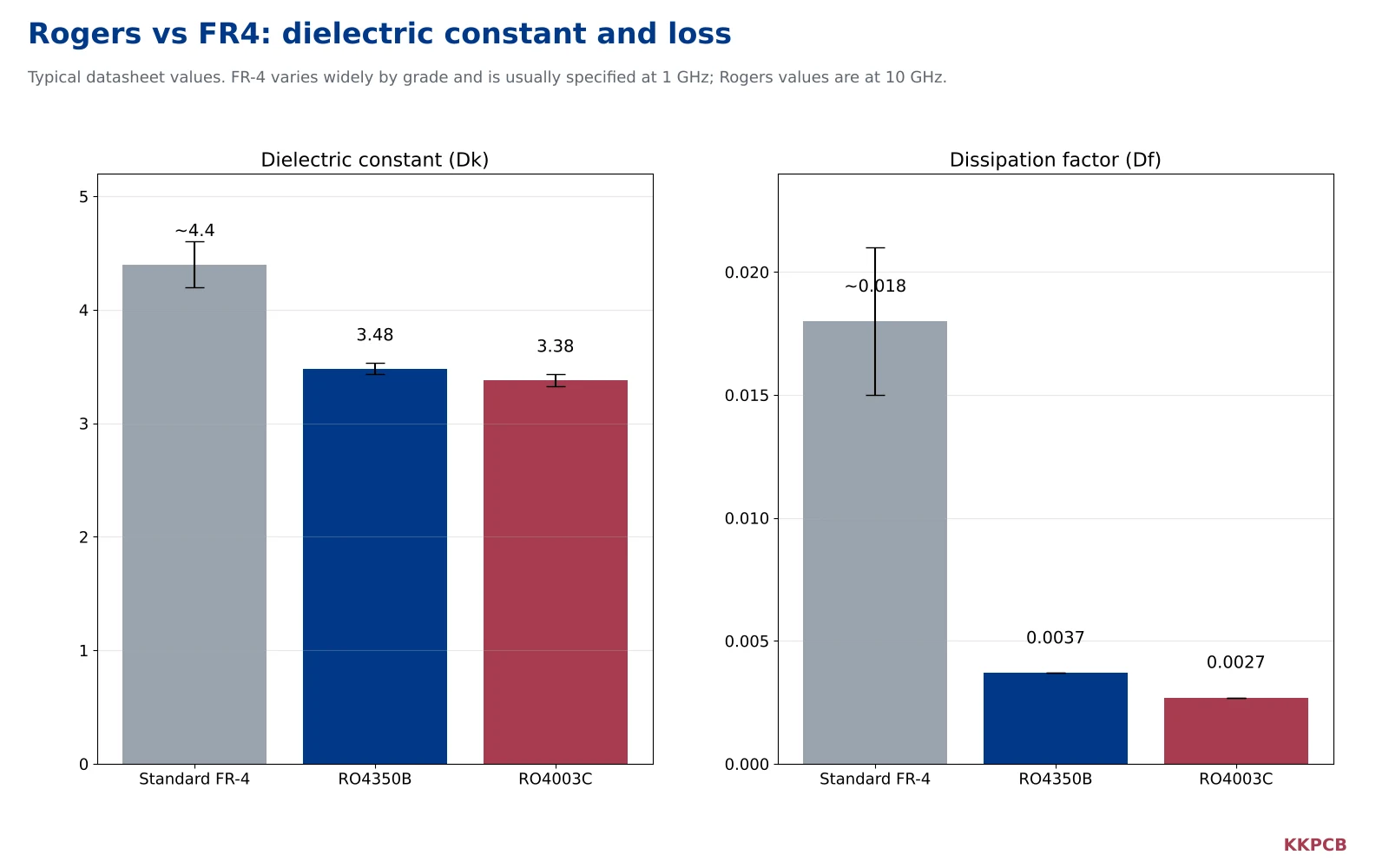
| Dielectric constant (Dk) | ~4.2–4.6, varies by grade and frequency | 3.48 ± 0.05 (10 GHz) | 3.38 ± 0.05 (10 GHz) |
| Dissipation factor (Df) | ~0.015–0.020 | 0.0037 (10 GHz) | 0.0027 (10 GHz) |
| Dk tolerance and stability | Wider; changes with resin content and glass style | Tight, specified by the manufacturer | Tight, specified by the manufacturer |
| Moisture absorption | Higher | Low | Low |
| Relative cost | Lowest | Higher | Higher |
Rogers values are typical datasheet figures. FR-4 values are indicative ranges; always use the datasheet of the specific laminate and the frequency of interest.
Dielectric loss (Df)
Dielectric loss grows with frequency and with trace length. With a Df several times lower than standard FR-4, a Rogers laminate loses far less signal over the same trace at microwave frequencies. For a short trace at a few hundred MHz the difference may be negligible; for a long feed network at 10 GHz or above it dominates the loss budget.
Dielectric constant and its tolerance
The dielectric constant sets trace impedance and electrical length. The absolute value matters less than its consistency: if Dk varies from panel to panel or across the board, impedance and phase vary with it. Engineered RF laminates specify Dk with a tight tolerance, which is why they are used for filters, couplers, antennas and phased arrays where phase matching matters.
Stability over frequency, temperature and humidity
FR-4 properties change more with frequency, temperature and moisture uptake. For outdoor radio equipment, automotive radar and satellite hardware, that variation becomes a design risk.
3. Common Rogers Laminates at a Glance
“Rogers” covers a wide family of materials. The table lists laminates that frequently appear in RF and radar designs, with typical datasheet values at 10 GHz.
| Material | Type | Dk (typical) | Df (typical) | Typical use |
|---|---|---|---|---|
| RO4003C | Hydrocarbon-ceramic | 3.38 | 0.0027 | Low-cost RF, antennas, amplifiers (not flame-retardant rated) |
| RO4350B | Hydrocarbon-ceramic | 3.48 | 0.0037 | General RF and microwave, hybrid boards (UL 94 V-0) |
| RO4835 | Hydrocarbon-ceramic | 3.48 | 0.0037 | Similar to RO4350B with improved oxidation resistance |
| RO3003 | PTFE-ceramic | 3.00 | 0.0010 | Millimetre-wave, automotive radar |
| RO3010 | PTFE-ceramic | 10.2 | 0.0022 | Miniaturized circuits needing high Dk |
| RT/duroid 5880 | PTFE-glass microfiber | 2.20 | 0.0009 | Very low-loss microwave, aerospace and antennas |
Values are typical figures from the manufacturer’s datasheets; confirm current datasheet values and the design Dk for your frequency before final impedance calculations.
Two practical observations follow from the table. First, the RO4000 family sits between FR-4 and PTFE materials: much lower loss than FR-4, but processed with methods close to FR-4. Second, the PTFE materials offer the lowest loss and are the usual choice at millimetre-wave frequencies, at the price of more demanding fabrication.
4. When FR-4 Is Good Enough
FR-4 remains the correct choice for a large share of RF-adjacent designs:
- Lower-frequency radio links with short RF traces between module and antenna connector.
- Digital boards with occasional high-speed interfaces, where a low-loss FR-4 grade or a high-speed laminate is more appropriate than a PTFE material.
- Products where cost is the main constraint and the RF section is a small, tested module.
For high-speed digital work, materials such as Megtron or other low-loss epoxy systems are often a better fit than Rogers; see our PCB materials overview.
5. When You Need Rogers
Rogers or another engineered RF laminate is usually justified when one or more of the following apply:
- Operating frequency in the microwave or millimetre-wave range, such as radar, satellite communication and 5G front ends.
- Long RF traces or feed networks where dielectric loss would consume the link budget.
- Phase-matched or tightly toleranced structures: filters, couplers, antenna arrays.
- Outdoor or temperature-cycling environments where stable Dk is required.
6. The Hybrid Option: Rogers + FR-4
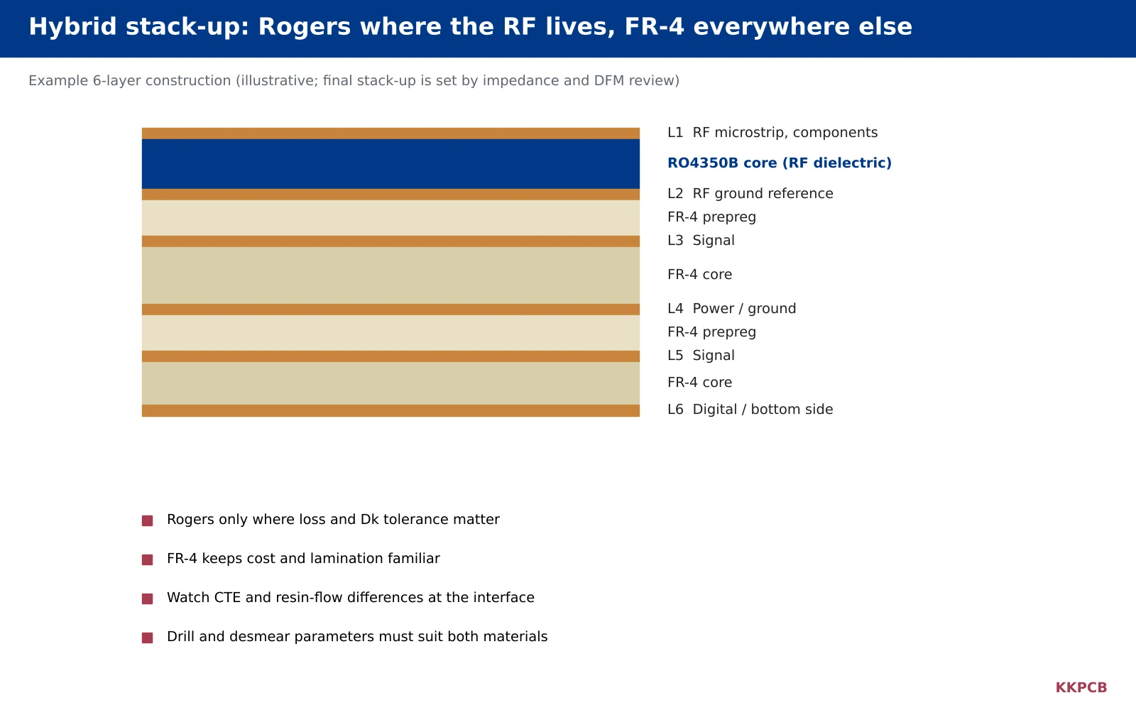
A hybrid stack-up places a Rogers laminate only on the layers that carry RF signals and uses FR-4 for the remaining layers. This combines RF performance with lower cost and the mechanical familiarity of FR-4. KKPCB builds high-frequency hybrid boards in 4–40 layers, combining Rogers, Taconic, Arlon or Wangling materials with FR-4.
Hybrid builds need specific attention:
- Different thermal expansion: the materials expand differently in the z-axis and in-plane, which affects warpage and via reliability.
- Lamination compatibility: resin flow and cure conditions must suit both materials.
- Drilling and hole preparation: drilling and desmear parameters must clean both dielectrics without damaging either. For PTFE and mixed materials KKPCB’s minimum drill is 0.25 mm.
- Impedance modelling: RF layers and digital layers are calculated with their own dielectric properties.
7. Rogers vs FR4 in PCB Manufacturing
| Process | FR-4 | RO4000 series | PTFE-based Rogers |
|---|---|---|---|
| Drilling | Standard | Close to FR-4; ceramic filler wears drills faster | Dedicated parameters; smearing risk |
| Hole wall preparation | Standard desmear | Standard methods, process-tuned | Special surface activation before plating |
| Lamination | Standard | Compatible prepregs available | Special bonding films and cycles |
| Dimensional stability | Good | Good | Softer; handling and registration need care |
These differences explain why PTFE-based boards cost more than their material price alone would suggest: they take more process time and more experienced handling.
8. Rogers vs FR4: Cost Considerations
Rogers laminates are significantly more expensive than standard FR-4, and PTFE materials add process cost on top. Practical ways to control cost are:
- Use Rogers only on RF layers through a hybrid stack-up.
- Choose the RO4000 series when its performance is sufficient, since it processes more like FR-4.
- Fit the board efficiently to the material panel size; KKPCB lists maximum board sizes by Rogers series on the high-frequency capabilities page.
- Agree the stack-up with your fabricator before layout so that standard core and prepreg thicknesses can be used.
9. Stack-Up and Impedance Considerations
Switching from FR-4 to Rogers changes more than the loss figure. Because the dielectric constant is lower, a 50 Ω microstrip on Rogers is wider than one on FR-4 of the same thickness. Several practical points follow:
- Recalculate every controlled-impedance trace with the design Dk of the chosen laminate at the operating frequency, not the FR-4 value.
- Use the fabricator’s actual dielectric thicknesses. RF laminates and their prepregs come in specific thicknesses; KKPCB’s high-frequency references list a minimum core thickness of 4 mil and specific Rogers prepregs such as RO4450F.
- Consider copper roughness. At high frequencies, rough copper increases conductor loss; low-profile copper foil can matter as much as the laminate choice.
- Plan the reference plane. In a hybrid board, the RF layer’s ground reference should be the copper directly beneath the Rogers dielectric so that the field stays in the low-loss material.
- Agree impedance tolerance. KKPCB’s standard tolerance is ±5 Ω below 50 Ω and ±10% at or above 50 Ω; tighter targets should be discussed before layout.
Sharing the target impedances, frequency range and proposed materials with the fabricator before routing allows the stack-up to be built from stocked materials and avoids redesigning trace widths late in the project.
Frequently Asked Questions
Rogers vs FR4: which is better?
For high-frequency performance, yes: lower loss and tighter dielectric-constant control. For cost, availability and general-purpose boards, FR-4 is usually the better choice. Many products use both in a hybrid stack-up.
At what frequency should I switch from FR4 to Rogers?
There is no single cut-off. The decision depends on frequency, trace length, loss budget and phase requirements. Short RF paths at lower GHz frequencies often work on FR-4, while microwave and millimetre-wave designs with longer traces usually need an engineered RF laminate.
Is RO4350B a PTFE material?
No. RO4350B is a hydrocarbon-ceramic laminate from the RO4000 family. It is designed to be processed with techniques close to FR-4, which is one reason it is widely used in RF and hybrid boards.
Can Rogers and FR4 be laminated together?
Yes. Hybrid Rogers + FR-4 stack-ups are common. They require compatible prepregs, adjusted lamination and drilling parameters, and careful impedance modelling.
Do Rogers boards need a special surface finish?
Not necessarily, but loss-sensitive RF traces often use immersion silver, OSP or a nickel-free finish instead of ENIG. See our comparison of HASL vs ENIG and the PCB surface finishes guide.
Get a Rogers vs FR4 Recommendation from KKPCB
KKPCB manufactures Rogers, Taconic, Arlon and PTFE high-frequency boards as well as Rogers + FR-4 hybrid stack-ups, and our engineers can review material choice, stack-up and impedance targets before you order. Further reading: High-Frequency PCBs for RF Applications.
Still deciding Rogers vs FR4? Contact KKPCB with your frequency range and stack-up for a material recommendation.
PCB fabrication at KKPCB follows the acceptance criteria of IPC (IPC-6012, IPC-A-600).