
Medical PCB rigid-flex design for a wearable device has to begin with motion, not only with the circuit diagram. The flex section may fold during assembly, bend during use, pass through an enclosure hinge, or absorb a connector transition. Each of those conditions changes the copper pattern, coverlay, stiffener placement, stackup, and assembly sequence. Treating the flex tail as a late routing extension can produce a board that is electrically connected but difficult to build or mechanically inconsistent.
The first design review should describe the mechanical path in plain terms: where the circuit bends, how often it moves, which surfaces contact the enclosure, where the neutral bend region lies, how the board is constrained, and what service or replacement route is expected. This information gives the PCB designer and fabricator a shared basis for deciding the flex construction.
Define bend zones before routing through them
Mark the bend zones and keep them visible in the controlled design data. Avoid placing vias, sharp copper corners, unsupported transitions, or unnecessary pads in a repeatedly flexed region. Route conductors with smooth geometry and consistent spacing where the circuit will bend; avoid an arbitrary trace pattern that concentrates stress at one narrow point. The permitted bend behavior depends on the specific construction, material set, thickness, and duty cycle, so obtain fabrication input before fixing the final route pattern.
The transition from rigid to flexible construction also deserves its own review. Copper balancing, coverlay openings, adhesive or adhesiveless materials, reinforcement, and the local mechanical load can all affect how the area behaves. A clear drawing of the intended fold direction and protected areas is more useful than leaving the fabricator to infer motion from a 3D model alone.
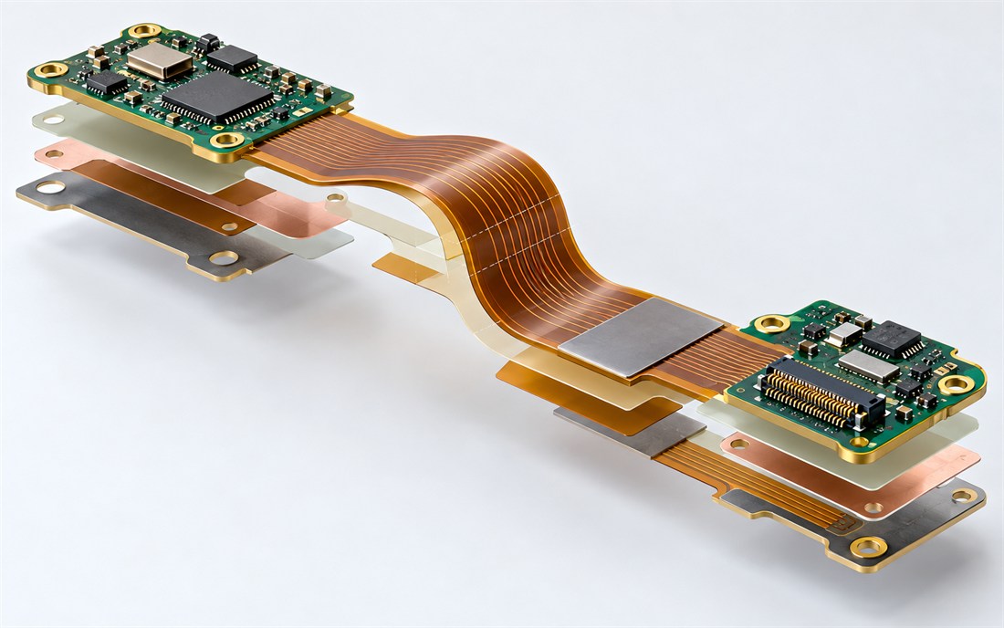
Use stiffeners for a defined purpose
Stiffeners can support a connector, create a handling area, control local thickness, or reinforce a transition. They should not be treated as universal insurance. A stiffener that ends abruptly in a flex path can create a new stress concentration; one that extends into a required bend zone can work against the motion the product needs. Define the material, thickness, outline, adhesive area, and location in the fabrication data, and show how it relates to the enclosure and assembly fixtures.
Connector choice is equally mechanical. The retention method, insertion direction, cable or flex exit, service access, strain-relief feature, and mating cycle all influence the local circuit design. Coordinate the connector footprint with the board thickness, stiffener plan, copper keep-outs, and enclosure bosses rather than reviewing it solely as a library symbol.
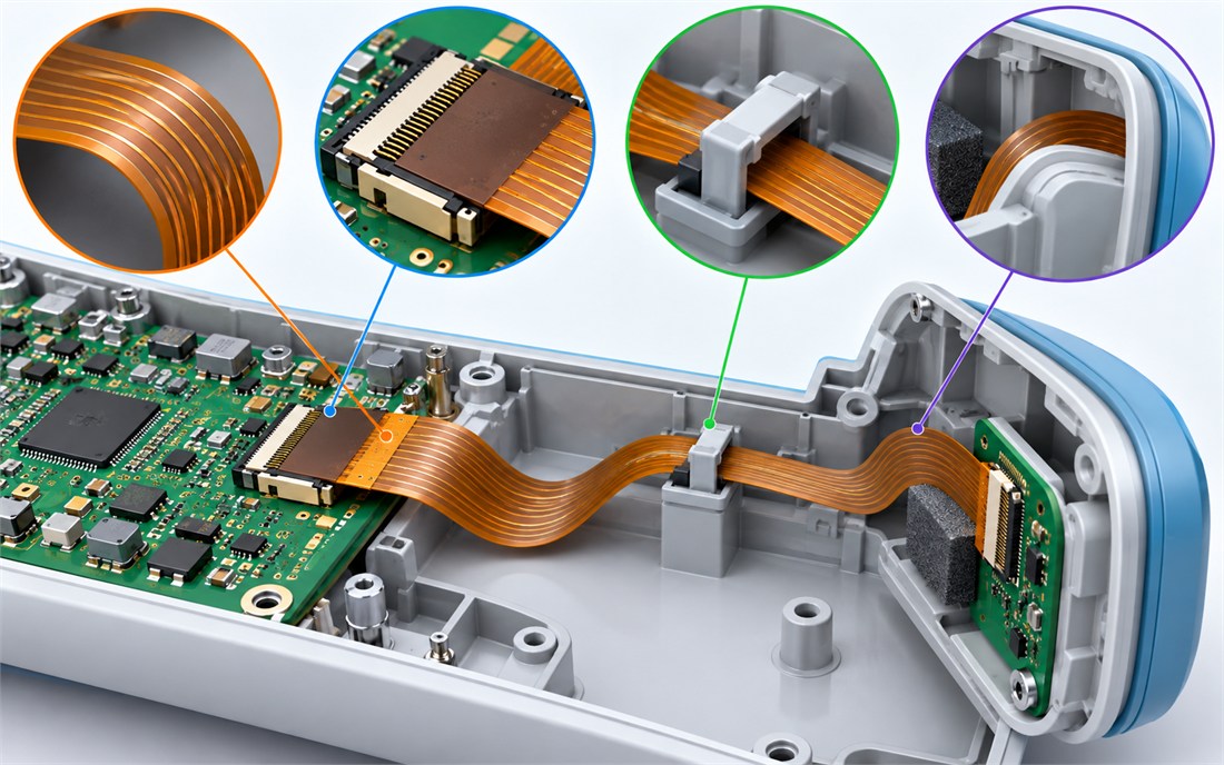
Coordinate fabrication, assembly, and enclosure interfaces
Rigid-flex production crosses several disciplines: fabrication of the multilayer construction, flex handling, surface finish, component assembly, fixture support, enclosure installation, and final inspection. Share a controlled package that includes the stackup, flex layer construction, coverlay and stiffener details, bend notes, component keep-outs, controlled thicknesses, drawings, and a 3D or mechanical reference where available. Early questions from the fabricator or assembler are useful design input, not a sign that the drawing is incomplete.
Plan the assembly sequence around the delicate areas. A flex tail may need fixture support during reflow or test; a connector may require a reinforcement before mating; and an enclosure may impose a final bend that should not be used as a production handling step. Document the agreed method so that a prototype workaround does not become an unrecorded production process.
Finish with a mechanical and electrical review
Before release, review the flex route in its installed shape, not only flattened in CAD. Check bend zones, copper geometry, stiffener ends, connector orientation, board-to-enclosure clearance, test access, and any sharp edges or pinching points. Then verify that the fabrication drawing and assembly notes express the same intent. This final step is especially valuable when a wearable product is revised for a new enclosure or connector, because small mechanical changes can alter the practical behavior of the flex circuit.
Five rigid-flex checks before release
- Mark bend zones and fold direction in the controlled design data.
- Keep vias, abrupt copper geometry, and unnecessary pads out of repeated bends.
- Define stiffener material, thickness, outline, and termination locations.
- Review connector retention, strain relief, and enclosure support as one interface.
- Inspect the installed mechanical shape as well as the flattened CAD layout.
Source note: Bend-life, environmental, and safety requirements are product-specific. This general design guidance does not establish a performance rating or product certification.
Related KKPCB capabilities
- Medical PCB planning for sensor, power, and mechanical interfaces.
- Medical PCB manufacturing review before a released data package.
- Medical PCB build discussions with fabrication and assembly inputs aligned.
- Medical PCB DFM communication for controlled production changes.
- Medical PCB projects that need documented handoff decisions.
- PCB Manufacturing options for stackup, materials, and fabrication data review.
- High Frequency PCB know-how when signal behavior must be considered early.
- HDI PCB approaches for dense interconnect and constrained routing.
- Multilayer PCB construction support for planned reference planes and routing layers.
- PCB Prototype builds for checking the released design before a larger run.
- Rigid-Flex PCB coordination where mechanical motion shapes the circuit.
- PCB Assembly review for process-sensitive component and cleaning choices.
- PCB Prototype Assembly support for early build learning.
- BGA PCB Assembly considerations for fine-pitch component placement and inspection planning.
- SMT PCB Assembly process input for repeatable component placement and reflow.
