
Table of Contents
A LoRa PCB can meet its bench range target and then behave differently after conformal coating, cleaning, or enclosure sealing. The LoRa PCB must be released in the same coated state used for comparison. The change is often blamed on the radio or antenna, but the real cause is a process boundary: coating may enter the keep-out, moisture may remain under a shield, or a cleaning step may leave residue near the feed. For an outdoor product, the coating plan and the RF release plan must describe the same board state.
Why coating can change a range result
An antenna responds to the material around its radiator and feed. A thin coating layer, a trapped pocket of solvent, or a wet enclosure vent can alter the local dielectric environment. The effect does not need to be large to matter when the design has little tuning margin. A LoRa PCB review should therefore identify which surfaces are intended to be coated, which must remain clean, and how the board will be supported during application.
Start by separating three states: bare board, assembled board before coating, and finished coated assembly. A coating boundary review should show the antenna, matching parts, connector, shield edge, and test pads in each state. Do not use a generic keep-out copied from another radio. The antenna vendor drawing, enclosure wall, and production spray direction all influence the boundary.
Protect the LoRa PCB antenna boundary before coating
Masking is a design feature, not an operator preference. Define a mask shape that protects the radiator and leaves the matching network accessible for inspection. Keep the mask edge away from the feed transition so a ragged coating line does not create a variable capacitive feature. The ground return under the feed should remain continuous, and any via fence should be visible after the mask is removed. A LoRa PCB layout check should compare the mask drawing with the copper and silkscreen layers rather than relying on a screenshot.
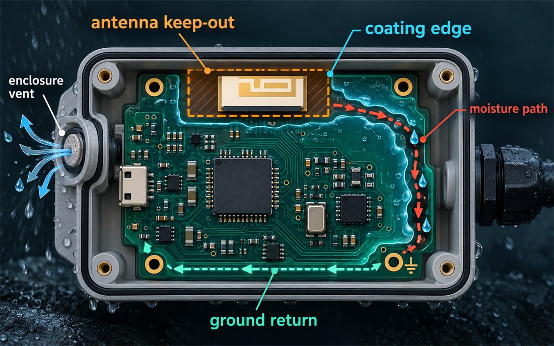
This conceptual figure shows an antenna keep-out, coating edge, moisture path, and ground return. It is not a measured environmental result. For production, lock the masking and keep-out specification with the same revision as the board drawing. If a coating supplier changes viscosity or spray method, route the change through engineering review instead of assuming the original RF margin still applies.
Keep materials and finishes inside the evidence boundary
The laminate, solder mask, surface finish, adhesive, and coating all contribute to the final stack around the radiator. The laminate and finish review should record the approved construction and any no-clean or cleaning chemistry assumptions. Typical material values may guide design, but a project should not present them as a finished-board measurement. When the antenna is close to a metal wall, even a small process change deserves a new comparison.
Control cleaning, masking, and cure
Cleaning can move contamination into the exact place where the antenna is most sensitive. Flux residue, solvent, or water trapped beneath a shield may change loss and create corrosion risk. Define the cleaning-process window and the drying condition before the first article. A board that is tested immediately after washing is not equivalent to a board that has reached the approved dry state.
During coating, control board orientation, spray distance, mask installation, and cure time. The operator should be able to identify the antenna boundary without guessing from component outlines. The fixture-support plan must prevent the board from moving while the coating is wet. If a shield can or connector is installed later, its seating pressure and soldering sequence should be part of the same traveler.
Verify the coated assembly without false comparisons
Use a repeatable sequence for environmental verification: inspect the mask edge, confirm coating coverage, check connector and shield seating, and then perform the approved RF comparison. Capture the board revision, coating lot, cure state, enclosure, cable orientation, and fixture ID. The coating-inspection record should include photographs or dimensional observations where they are allowed, but never imply that a conceptual diagram is a test report.
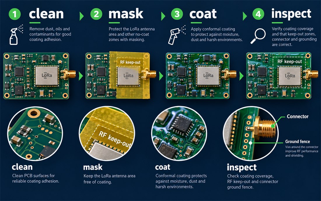
The second conceptual figure represents a clean–mask–coat–inspect workflow. It is intended to clarify handoff points, not to claim a customer result. A return-path inspection should confirm that coating or residue has not bridged a sensitive gap. Check the antenna feed, ground fence, matching components, and any exposed test pad before the board enters a chamber or field trial.
Separate target values from measured evidence
Engineering teams may use a target sensitivity, a design frequency range, or a moisture-handling review during development. Those are useful planning values, but they are not measured evidence. A LoRa PCB release package should label each value as a typical material value, a design target, an engineering range, or a measured result. This makes it easier for a project manager to decide what must be repeated when the coating supplier, enclosure vent, or cleaning chemistry changes.
A release checklist for environmental builds
- Show bare, assembled, and coated board states in the antenna and enclosure drawing.
- Dimension the mask boundary from the antenna datum and keep the feed and return path inspectable.
- Lock laminate, solder mask, surface finish, coating chemistry, cleaning method, and cure assumptions.
- Define fixture support, board orientation, spray or dispense direction, and drying condition.
- Record coating lot, board revision, enclosure state, cable position, and RF comparison method.
- Route any mask, coating, supplier, or antenna-boundary change through the environmental change review.
When process state is controlled, the finished LoRa PCB has a traceable environmental boundary. a LoRa PCB can move from prototype tuning to outdoor assembly without hiding a coating variable inside the RF result. The goal is not to promise a universal range number; it is to make the antenna boundary, materials, and environmental evidence repeatable enough for a confident production decision.
Sources: Taconic RF laminate technical data and application guidance; Würth Elektronik RF layout and coating/assembly notes; Analog Devices grounding and environmental design guidance; Qorvo antenna and front-end integration documentation. Values and process checks above are engineering practices or design targets, not customer measurements.
