Introduction to UAV PCB

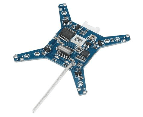
A UAV PCB is a specialized printed circuit board engineered for unmanned aerial vehicle systems. Drones integrate flight control, power management, communication modules, GPS navigation, sensors, and imaging systems into a compact and lightweight structure.
The PCB acts as the central platform that connects and coordinates all electronic subsystems while maintaining stability under vibration, rapid acceleration, and varying environmental conditions.
System Architecture Requirements
Modern UAV systems typically include:
-
Flight control unit (FCU)
-
ESC (Electronic Speed Controller)
-
GPS module
-
IMU sensors
-
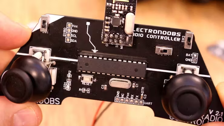
RF communication module
-
Camera transmission system
-
Battery management system
A UAV PCB must support multi-layer integration while keeping signal routing clean and power distribution stable.
Key Design Considerations
1. Lightweight Construction
Weight directly affects flight time and efficiency. PCB designers often use:
-
Optimized board thickness
-
Controlled copper weight
-
Compact multilayer stack-up
-
HDI structures when needed
Reducing unnecessary copper areas and using balanced stack designs helps minimize total mass.
2. High Vibration and Shock Resistance
During flight, UAVs experience:
-
Continuous motor vibration
-
Sudden directional changes
-
Impact during landing
Design strategies include:
-
Reinforced mounting points
-
Shorter trace lengths
-
Stable component placement
-
Symmetrical stack-up to reduce warpage
Mechanical durability is critical for long-term operation.
3. Stable Power Distribution
UAV systems often operate at:
-
3.3V / 5V logic supply
-
12V or higher motor supply
-
Lithium battery input
High-current paths must be carefully designed to prevent voltage drop and overheating. Thick copper or dedicated power planes are commonly used for ESC and motor control circuits.
4. High-Frequency Communication Stability
UAVs rely heavily on RF communication for:
-
Remote control signals
-
Real-time video transmission
-
GPS signal reception
PCB design must support:
-
Controlled impedance routing
-
Ground shielding
-
Short RF trace length
-
Clean return paths
Stable RF layout ensures reliable long-distance communication.
5. EMI and Signal Integrity Control
Motors and switching regulators generate electrical noise that can interfere with sensitive sensors.
Proper PCB design includes:
-
Ground plane separation
-
Decoupling capacitor placement
-
Filter circuits
-
Careful analog and digital partitioning
Effective EMI management improves flight stability and navigation accuracy.
Typical UAV PCB Structures
Depending on system complexity, UAV PCBs may include:
-
Multilayer boards (4–8 layers common)
-
HDI boards for compact drones
-
Heavy copper sections for ESC modules
-
Hybrid stack-ups combining power and signal layers
Material selection depends on thermal demand and reliability targets.
Applications of UAV PCB
UAV PCBs are widely used in:
-
Consumer drones
-
Industrial inspection drones
-
Agricultural spraying UAVs
-
Mapping and surveying drones
-
Defense and security UAV systems
-
Logistics and delivery drones
As drone capabilities expand, PCB integration becomes more sophisticated.
UAV PCB vs Standard Control PCB
| Feature | Standard PCB | UAV PCB |
|---|---|---|
| Weight Sensitivity | Moderate | Critical |
| Vibration Resistance | Standard | High |
| RF Integration | Limited | Essential |
| Power Density | Moderate | High |
| Environmental Stability | Normal | Enhanced |
UAV PCB design focuses on performance optimization under dynamic operating conditions.
Conclusion

UAV PCB technology supports lightweight design, stable power distribution, and reliable high-frequency communication in modern drone systems. Through careful layout planning, vibration-resistant structures, and signal integrity optimization, UAV PCBs ensure safe and efficient flight performance.
As UAV applications continue expanding into industrial and commercial sectors, advanced PCB engineering plays a key role in improving reliability, endurance, and system integration.
