As modern electronics move into higher frequencies and higher data rates, the PCB material selection becomes a key factor in system performance. For applications such as RF communication, microwave circuits, 5G infrastructure, radar sensing, and satellite systems, signal loss and impedance instability can quickly become major challenges.
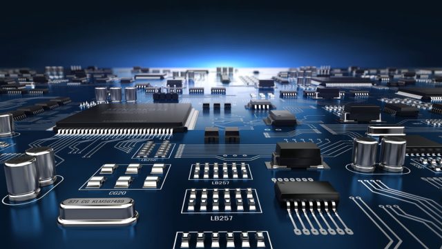
That’s why PTFE PCB (Polytetrafluoroethylene PCB), often referred to as Teflon PCB, is widely used in high-frequency designs. PTFE-based laminates provide excellent electrical stability and ultra-low loss, making them one of the most trusted materials for RF and microwave circuit boards.
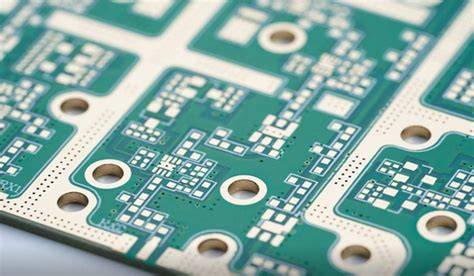
What Is a PTFE PCB?
A PTFE PCB is a printed circuit board manufactured using PTFE-based high-frequency laminate materials. PTFE is known for its outstanding dielectric properties, including:
-
Low dielectric constant (Dk)
-
Very low dissipation factor (Df)
-
Stable electrical performance at high frequencies
Because of these advantages, PTFE PCBs are commonly selected for demanding applications where standard FR4 materials cannot meet RF performance requirements.
Key Benefits of PTFE PCB
1. Ultra-Low Dielectric Loss (Low Df)
PTFE materials provide extremely low dielectric loss, helping reduce signal attenuation during transmission. This leads to:
-
Lower insertion loss
-
Higher RF efficiency
-
Improved signal strength and clarity
For microwave and high-frequency signals, this is one of the most important performance benefits.
2. Stable Dielectric Constant (Dk) for Reliable Impedance Control
Controlled impedance is critical for RF transmission lines such as 50Ω microstrip or stripline structures. PTFE PCB materials offer stable Dk performance, supporting:
-
Accurate impedance matching
-
Reduced signal reflection
-
Consistent phase performance
This is especially important in antennas, filters, couplers, and RF feed networks.
3. Excellent RF & Microwave Performance
PTFE PCB is designed for high-frequency operation, making it suitable for:
-
RF front-end circuits
-
Microwave power amplifiers
-
High-frequency filters and mixers
-
Precision antenna modules
PTFE helps improve overall RF system performance by maintaining low loss and stable electrical characteristics.
4. High Reliability for Demanding Environments
PTFE PCBs are often used in industries where reliability is critical. With proper design and manufacturing control, PTFE PCBs can perform well in:
-
Outdoor telecom equipment
-
Automotive radar systems
-
Aerospace and satellite electronics
-
High-power RF modules
Common Applications of PTFE PCB
PTFE PCBs are widely used across high-frequency industries, including:
Antennas and Wireless Modules
PTFE PCB is commonly used for:
-
Patch antennas
-
Antenna arrays
-
Wi-Fi and GPS antenna boards
Its low loss performance improves antenna efficiency and signal stability.
5G and Telecom Equipment
In 5G systems, PTFE PCB is used in:
-
Base station RF modules
-
Small cell systems
-
RF signal distribution networks
Low insertion loss is essential for maintaining performance at higher frequency bands.
Radar Systems (Automotive & Industrial)
PTFE PCB supports radar applications such as:
-
24GHz / 77GHz radar modules
-
ADAS sensing systems
-
Industrial radar detection
Stable Dk and low loss help maintain consistent radar signal performance.
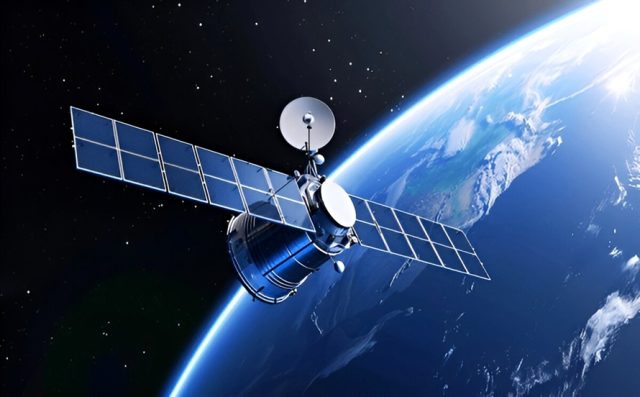
Satellite and Aerospace Communication
PTFE PCB is widely used in:
-
Satellite RF modules
-
Aerospace microwave systems
-
High-reliability navigation equipment
These applications require strong signal integrity and long-term stability.
PTFE PCB vs FR4: Why PTFE Performs Better at High Frequencies
FR4 is a cost-effective standard PCB material, but it becomes less suitable at high frequencies due to higher dielectric loss and unstable electrical properties.
| Feature | FR4 PCB | PTFE PCB |
|---|---|---|
| Dielectric Loss | Higher | Much lower |
| Dk Stability | Moderate | Excellent |
| RF/Microwave Performance | Limited | Strong |
| Controlled Impedance | Less consistent | Highly consistent |
| Typical Applications | General electronics | RF & microwave circuits |
If your design requires low loss and stable RF performance, PTFE PCB is usually a better material choice.
Manufacturing Considerations for PTFE PCB
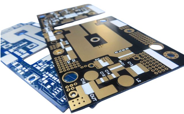
Producing PTFE PCBs requires specialized experience and process control because PTFE-based materials behave differently than standard FR4.
Key considerations include:
Material Handling and Lamination Control
PTFE laminates require optimized lamination parameters to ensure:
-
Strong bonding
-
Stable dielectric thickness
-
Reduced risk of delamination
Precision Etching for RF Trace Accuracy
High-frequency performance depends heavily on trace geometry. Tight control of:
-
Trace width
-
Copper thickness
-
Etching tolerance
helps maintain consistent impedance and stable RF behavior.
Drilling and Via Quality
PTFE PCB drilling and plating must be well-controlled to ensure:
-
Reliable via connections
-
Stable signal transitions
-
Strong thermal cycling reliability
Controlled Impedance Testing
For RF transmission lines, impedance testing helps confirm the PCB meets design targets and performance requirements.
Conclusion
PTFE PCB is one of the most reliable material choices for RF and microwave applications thanks to its ultra-low loss, stable dielectric performance, and excellent signal integrity. It is widely used in 5G systems, antennas, radar modules, satellite communication, and aerospace electronics, helping engineers achieve stable high-frequency performance beyond what FR4 can offer.
If your project requires low insertion loss and consistent impedance control, PTFE PCB is an ideal solution for high-frequency circuit design.
