Advanced driver-assistance systems (ADAS) rely heavily on multi-sensor fusion, where radar, LiDAR, ultrasonic sensing, and camera modules continuously exchange high-frequency data. To maintain real-time performance and safety-critical reliability, the ADAS PCB must deliver low-loss signal transmission, stable dielectric behavior, and tight impedance control under prolonged automotive thermal and vibration stress.
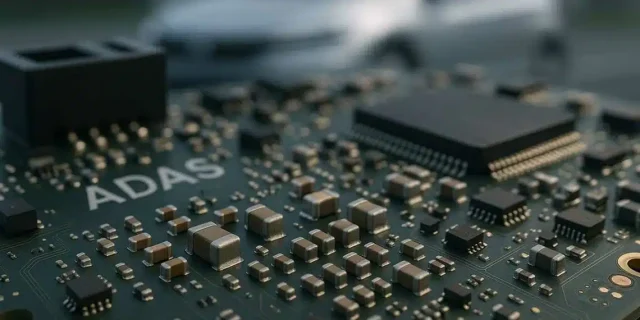
High-frequency ADAS RF chains—particularly 24 GHz, 60 GHz, and 77/79 GHz radar interfaces—place extraordinary electrical demands on PCB materials. Conventional FR-4 rapidly loses integrity under high-frequency loading, while temperature cycling degrades phase alignment. This is why automotive Tier-1s increasingly adopt RO4350B PCB, RO4835 PCB, and other high-frequency ADAS PCB materials, which maintain stable Dk/Df, predictable impedance, and low dissipation factors essential for multi-sensor fusion.
Material Engineering for ADAS Multi-Sensor Fusion
ADAS sensor fusion modules require PCB substrates with:
-
Low-loss dielectric behavior to prevent attenuation of high-frequency radar and data interconnects
-
Stable dielectric constant (Dk) and dissipation factor (Df) across –40 °C to +140 °C
-
Low moisture absorption to maintain phase stability and SNR in real-world humidity
-
Tight impedance windows (±5% or better) for differential radar data channels
-
High Tg and low CTE to survive automotive thermal cycling and engine-bay harsh environments
Materials such as RO4350B PCB (Dk 3.48, Df 0.0037) and RO4835 PCB provide stable high-frequency properties and ultra-low insertion loss profiles that preserve the integrity of multi-sensor fusion pipelines.
Core Engineering Challenges in ADAS Fusion Modules
1. High-Frequency Loss and Signal Attenuation
Radar and high-speed SerDes lanes demand low-loss PCB materials; otherwise, SNR rapidly collapses. ADAS PCB stackups using RO4350B or RO4835 suppress dielectric loss and maintain channel linearity under full load.
2. Thermal-Induced Drift and Impedance Instability
Sensor fusion requires synchronized phase and timing. Low-CTE laminates minimize drift across repeated automotive thermal cycling.
3. Crosstalk and Mode Conversion in Dense Sensor Routing
Fusion modules combine radar, camera, and computing paths on the same PCB. High-frequency ADAS layouts rely on engineered ground referencing, differential pair control, and spacing rules to keep interference below acceptable limits.
4. Long-Term Reliability and Environmental Stress
Moisture, vibration, and shock degrade conventional boards; ADAS PCB materials are engineered for long-term dielectric stability, protecting fusion algorithms from corrupted inputs.
KKPCB Engineering Approach for ADAS PCB Platforms
To guarantee stable multi-sensor fusion performance, KKPCB uses:
-
Multilayer low-loss ADAS PCB stackups combining RO4350B / RO4835 with controlled copper roughness
-
Precision impedance modeling using HFSS + ADS + TDR validation
-
Phase-consistent routing for radar-to-processor timing alignment
-
Thermal FEM optimization to avoid hotspots under high CPU/GPU loads
-
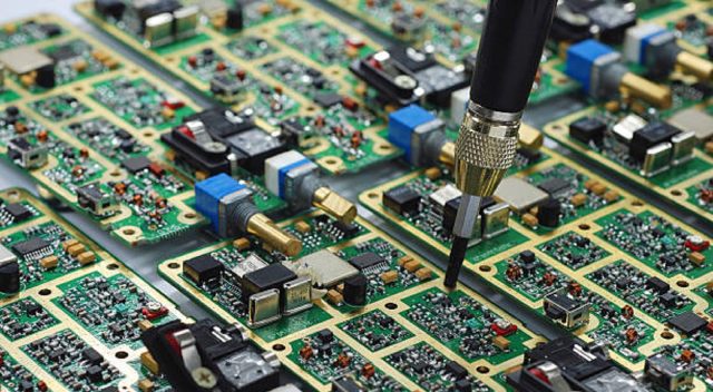
Automotive-grade manufacturing workflows (AOI, X-ray, reflow monitoring, 100% TDR sampling)
These workflows ensure the ADAS PCB remains stable over millions of kilometers and harsh environmental cycles.
Reliability Verification for Automotive Deployment

KKPCB validates each ADAS PCB against:
• Thermal Cycling: –40 °C to +125 °C for >1000 cycles
• Vibration / Shock: 10G, 5–2000 Hz for sensor module stability
• High-Humidity Aging: 85 °C/85% RH for dielectric consistency
• Radar Channel Phase Testing: Ensures synchronized multi-sensor outputs
• Long-Term Drift Monitoring: Stability of Dk/Df and impedance over service life
These evaluations ensure the multi-sensor fusion module maintains low-loss behavior, phase alignment, and long-term reliability in real-world autonomous driving conditions.
Engineering Summary
Advanced ADAS PCB materials—particularly RO4350B PCB and RO4835 PCB—are essential for building reliable, low-loss, and thermally stable multi-sensor fusion modules. Their combination of controlled Dk/Df, low insertion loss, and robust mechanical endurance ensures that data from radar, LiDAR, cameras, and ultrasonic sensors remains precise and synchronized.
KKPCB’s engineered ADAS PCB stackups further strengthen signal integrity, impedance control, and long-term reliability for next-generation autonomous driving platforms.
