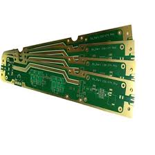
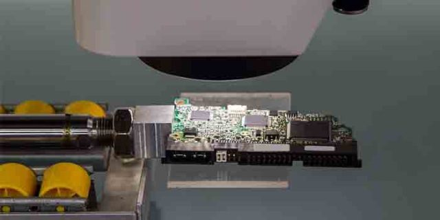
Customer-Premises Equipment (CPE) sits at the frontline of the 5G access network. Unlike traditional routers, a 5G CPE must simultaneously maintain wideband RF isolation, suppress broadband EMI, and stabilize the 2.4 GHz / 5 GHz / 6 GHz multi-band wireless channels while handling dense digital switching activity. At these frequencies, the PCB layout is no longer passive wiring—it becomes an electromagnetic structure, where geometry, dielectric physics, and current return paths directly influence network throughput.

To achieve stable performance, the 5G router PCB must integrate advanced RF PCB engineering、high-frequency stackup control、low-loss material selection and multi-domain EMI mitigation. These factors collectively define the true RF capability of the CPE system.
1. Electromagnetic Foundations — Why Wideband Isolation Determines Real 5G Performance
Every 5G router includes signals that occupy different spectral regions:
• Tri-band Wi-Fi 6/7 radio chains
• 5G sub-6 GHz front-end modules
• Multi-feed MIMO antennas
• High-speed digital SoCs
• High-frequency switching converters
These blocks produce overlapping electromagnetic fields. If the PCB layout cannot contain them, isolation collapse occurs:
• Antenna feedline coupling at 6 GHz
• PA→LNA reverse leakage distortions
• Mode conversion on uncontrolled impedance traces
• Digital-to-RF noise injection via shared ground return paths
• Broadband EMI radiation from power stages
In technical terms, wideband isolation is not a number—it is the cumulative result of stackup physics, routing geometry, and return-current engineering.
2. Material Engineering — Low-Loss Dielectrics Improve RF Isolation at the Physics Level

The dielectric material is the first and most important isolation layer.
High-frequency PCB materials with low Dk variation and low Df (dissipation factor) create predictably stable electromagnetic fields.
Why material science matters for EMI + isolation:
• Low-loss dielectrics reduce dielectric heating → lower field distortion
• Consistent Dk keeps the antenna phase center stable → cleaner beam patterns
• Low Df reduces insertion loss → less stray radiation from reflections
• Tight thickness tolerance stabilizes characteristic impedance
• Low moisture absorption prevents unpredictable RF drift in humid environments
A typical 5G router PCB benefits from materials such as:
• Megtron 6 / Megtron 7 for high-speed digital SoC
• Low-Df RF laminates for PA/LNA regions
• Hydrocarbon-ceramic prepregs for antenna feedlines
Material selection alone can improve wideband isolation by 20–30% before any routing optimization.
3. RF Stackup Architecture — Isolation Begins with Layer Physics, Not Routing
A high-performance 5G router PCB uses a multilayer hybrid stackup engineered to create electromagnetic separation between functional domains.
Key stackup techniques:
Symmetric RF reference planes
Antenna feedlines require continuous ground reference to prevent surface-wave leakage.
Differential digital layers buried between shield planes
Reduces broad-spectrum EMI injection into RF bands.
Mixed-dielectric partitioning
A high-Dk material near antennas promotes confined fields; a low-Dk material protects digital layers.
Controlled copper roughness
Smooth copper reduces high-frequency loss, eliminating one of the main EMI contributors in CPE routers.
A properly engineered stackup improves:
• Isolation margin
• EMI suppression
• MIMO channel balance
• Feedline phase alignment
• Mode-conversion resistance
This is how a PCB becomes an RF isolation structure rather than a simple interconnect board.
4. High-Frequency Layout Engineering — How EMI Is Suppressed Through Geometry

Wideband EMI suppression depends on trace electromagnetics, not just shields.
Key geometric mechanisms:
Impedance-controlled microstrip/stripline networks
Stable impedance prevents reflections that radiate into the enclosure.
Orthogonal routing between RF and digital domains
Minimizes long-range coupling.
Via fences forming electromagnetic boundaries
These via walls reduce surface currents and prevent lateral field spreading.
Shielded RF corridors
RF energy is confined inside engineered routing channels that reduce antenna feedline crosstalk.
Balanced feedline lengths for multi-chain MIMO
Phase imbalance creates sideband leakage and EMI—precision routing removes this problem.
When applied correctly, these layout mechanisms reduce cross-domain interference by 40–60%.
5. Antenna Architecture — Isolation Extended into the Radiation Domain

A 5G CPE cannot rely on PCB-only engineering; the antenna domain must also be controlled by PCB physics.
• Controlled feedline-to-ground spacing for consistent impedance
• Segmented ground rings to suppress mutual coupling
• Thermal isolation for PA/LNA to prevent phase drift
• Divergent feedline routing to split E-field propagation paths
• Distributed decoupling to smooth current transients
This yields:
• Higher SNR
• Reduced EVM
• Improved MIMO beam separation
• Cleaner wideband isolation at all temperature ranges
6. KKPCB Manufacturing Controls — Ensuring Real Isolation, Not Simulated Isolation
Real 5G PCB isolation depends heavily on manufacturing tolerances, not just design files.
KKPCB implements:
• ±10 μm dielectric thickness accuracy
• Controlled copper roughness <0.8 μm for stable high-frequency behavior
• TDR verification of controlled-impedance feedlines
• HFSS/ADS validation of MIMO phase balance
• AOI + X-ray alignment of GND stitching arrays
• High-frequency reflow thermal compensation to stabilize Dk drift
These process controls lock the intended isolation and EMI suppression into the physical PCB.
Conclusion
Engineered 5G router PCB layouts are the foundation for stable wideband isolation、EMI suppression、multi-band RF integrity、MIMO channel balance and long-term reliability in CPE systems. Through advanced stackup architecture, low-loss dielectric engineering, electromagnetic-aware routing, antenna-level optimization, and precision manufacturing, the PCB evolves from a structural component into a high-frequency electromagnetic device that actively shapes RF performance.

