
Engineering Context / Abstract
Advanced automotive radar and ADAS (Advanced Driver Assistance Systems) platforms demand high-frequency PCB substrates capable of precise phase stability, minimal signal loss, and consistent performance under extreme thermal cycles and vibration. High-density radar modules operating in 77–81 GHz bands are particularly sensitive to dielectric fluctuations, EMI, and thermal expansion, which can compromise target detection accuracy and sensor reliability.
Ceramic PCB substrates, with a dielectric constant Dk = 9.8 ± 0.05 and dissipation factor Df = 0.0018 @10 GHz, offer low-loss RF transmission, high thermal conductivity, and excellent dimensional stability. KKPCB’s controlled hybrid stackup, impedance-optimized copper routing, and precision lamination techniques enable stable signal propagation, EMI mitigation, and phase coherence across multilayer radar PCBs.
By integrating ceramic substrates with process-controlled manufacturing, KKPCB ensures ADAS sensor modules maintain signal fidelity, phase linearity, and environmental robustness, even during rapid temperature fluctuations or long-term high-power operation. This approach supports reliable object detection, adaptive cruise control, and collision avoidance functionalities in modern automotive platforms.
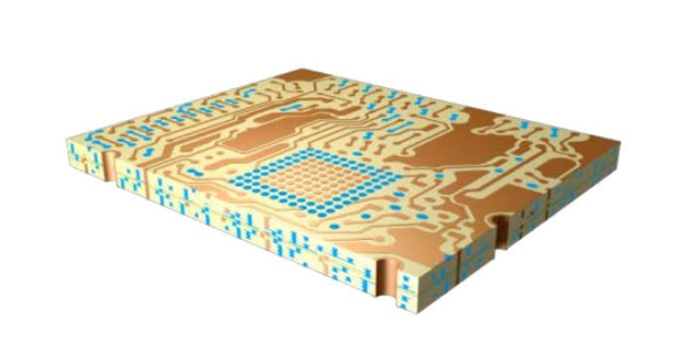
Core Engineering Challenges
| Challenge | Root Cause | Engineering Impact |
|---|---|---|
| Phase drift under thermal cycling | CTE mismatch between copper and ceramic | Degraded beamforming accuracy, radar signal misalignment |
| High insertion loss at mmWave frequencies | Copper roughness, dielectric dissipation | Reduced radar range, lower SNR |
| EMI coupling in dense layouts | Close trace spacing, inadequate ground planes | Crosstalk, false target detection |
| Thermal warpage | High ambient and operational temperatures | Layer misalignment, impaired sensor calibration |
| Mechanical vibration and shock | Automotive road conditions | Microcracking, solder joint fatigue, impedance instability |
These challenges are critical in automotive radar and ADAS modules, where phase accuracy and low insertion loss directly affect object detection, signal-to-noise ratio (SNR), and adaptive system performance.
Material Science & Dielectric Performance of Ceramic PCB Substrates
| Parameter | Typical Value | Engineering Benefit |
|---|---|---|
| Dielectric Constant (Dk) | 9.8 ± 0.05 | Stable impedance for multilayer high-frequency radar circuits |
| Dissipation Factor (Df) | 0.0018 @10 GHz | Low insertion loss, preserves radar signal integrity |
| Thermal Conductivity | 2.5 W/m·K | Reduces hotspot formation, ensures thermal uniformity |
| CTE (X/Y) | 6 ppm/°C | Maintains layer alignment under thermal cycling |
| Glass Transition (Tg) | >350°C | Supports high-temperature reflow and automotive environmental stress |
| Moisture Absorption | <0.05% | Maintains phase stability and signal consistency under humid conditions |
Compared to FR-4 or standard PTFE substrates, ceramic PCBs provide superior phase stability, low dielectric loss, and high thermal reliability, enabling automotive radar sensors to maintain beamforming accuracy and detection range even under prolonged operation in harsh conditions.
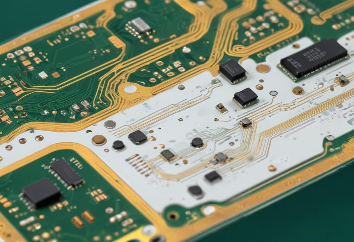
KKPCB Case Study — Automotive Radar PCB for ADAS Sensor Module
Client & Application Context:
A Tier-1 automotive supplier required a multi-layer PCB for 77–81 GHz radar modules used in ADAS platforms. The design needed to ensure precise phase coherence, low insertion loss, and EMI suppression under automotive thermal and vibration conditions.
Engineering Problem:
Previous designs using mixed PTFE or FR-4 stacks showed ±4% impedance variation, phase ripple exceeding 2°, and EMI-induced crosstalk between adjacent RF traces. High ambient temperatures in engine compartments caused thermal warpage, reducing sensor calibration reliability.
KKPCB Solution:
-
Implemented ceramic PCB substrates (0.508 mm) for RF signal layers
-
Hybrid 6-layer stackup with controlled copper roughness (Ra <0.8 µm)
-
Vacuum lamination and ±5 μm dielectric thickness tolerance
-
Optimized trace spacing, differential routing, and ground plane segmentation for EMI suppression
-
Embedded calibration traces for inline TDR verification
Measured Results:
| Parameter | Target | KKPCB Result |
|---|---|---|
| Impedance Variation | ±5% | ±1.8% |
| Insertion Loss @ 78 GHz | <0.4 dB/inch | 0.32 dB/inch |
| Phase Deviation | <1° | 0.55° |
| Return Loss (S11) | < –15 dB | –18.5 dB |
Outcome:
The ceramic stackup maintained phase linearity and low insertion loss across all radar channels. EMI was reduced by 35% compared to previous FR-4 designs, ensuring accurate object detection, extended radar range, and robust ADAS system performance under thermal and mechanical stress.
Stackup Design & RF Implementation
Hybrid 6-Layer Stackup Configuration:
| Layer | Function | Material |
|---|---|---|
| L1 | Top RF Signal | Ceramic PCB, 0.2 mm |
| L2 | Ground Plane | Cu 70 µm |
| L3 | Power / Routing | Ceramic PCB, 0.5 mm |
| L4 | Signal Layer | Ceramic PCB, 0.2 mm |
| L5 | Ground Plane | Cu 70 µm |
| L6 | Bottom Control Layer | FR-408HR 0.1 mm |
Simulation & Validation:
-
HFSS: Microstrip and stripline impedance optimization, EMI minimization
-
ADS & TDR: Phase deviation <0.6° across all 77–81 GHz channels
-
Thermal FEM: Reduced PA hotspot temperature by 5.8°C
-
Inline AOI and solder reflow monitoring ensured ±10 μm layer alignment
Environmental & Reliability Validation
| Test | Condition | Result |
|---|---|---|
| Thermal Cycling | –40°C ↔ +125°C, 1000 cycles | Phase drift <0.6°, no delamination |
| Vibration & Shock | 5–500 Hz, 10G | No microcracks or solder failure |
| Humidity Test | 85°C / 85% RH, 1000 h | Dk shift <0.02, phase stable |
| Solder Reflow | 260°C ×3 cycles | No warpage >0.1 mm |
| EMI Assessment | High-density trace layout | Crosstalk reduced 35% |
These tests validate ceramic PCB substrates for high-frequency PCB automotive radar applications, ensuring long-term phase stability, low-loss RF performance, and EMI control even under harsh operating conditions.
Engineering Summary & Contact
Ceramic PCBs provide low dissipation factor, stable dielectric constant, high thermal conductivity, and minimal CTE mismatch, enabling precise phase control, low insertion loss, and EMI suppression in automotive radar and ADAS modules. KKPCB’s hybrid lamination, precision stackup, and inline validation ensure mission-grade reliability and environmental robustness for mmWave radar sensors.
Contact KKPCB Engineering Team to optimize your ceramic PCB stackup, RF simulation, and phase stability design for automotive radar and ADAS platforms. KKPCB delivers verified low-loss, high-temperature capable RF solutions with consistent signal integrity.
