
Automotive radar has become one of the most important sensing technologies in modern Advanced Driver Assistance Systems (ADAS) and autonomous driving platforms. By transmitting and receiving high-frequency electromagnetic signals, radar systems enable vehicles to accurately detect distance, speed, and object movement in complex environments.
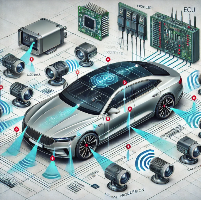
At the center of every high-performance radar module is the Automotive Radar PCB — a critical RF platform responsible for maintaining signal integrity, impedance consistency, thermal stability, and long-term reliability.
Unlike conventional digital PCBs, automotive radar PCBs operate at millimeter-wave frequencies, typically including:
- 24 GHz radar systems
- 77 GHz automotive radar
- Emerging 79–81 GHz radar applications
At these frequencies, even small variations in PCB materials, trace geometry, or manufacturing processes can significantly influence radar accuracy.
KKPCB specializes in manufacturing high-frequency and RF PCBs for automotive radar applications, combining advanced material technology, precision fabrication, and strict quality control to support reliable radar performance in demanding automotive environments.
The Growing Importance of Automotive Radar Systems
Automotive radar systems provide vehicles with environmental perception capabilities by analyzing reflected RF signals.
They are widely used in ADAS functions including:
- Adaptive Cruise Control (ACC)
- Forward Collision Warning (FCW)
- Autonomous Emergency Braking (AEB)
- Blind Spot Detection (BSD)
- Lane Change Assistance (LCA)
- Cross Traffic Alert (CTA)
Compared with earlier 24 GHz radar solutions, 77 GHz millimeter-wave radar technology offers:
- Higher resolution
- Longer detection range
- Smaller antenna size
- Improved object recognition capability
However, higher operating frequencies also introduce stricter PCB requirements. The radar PCB is no longer simply a connection platform — it becomes a key component that directly affects electromagnetic performance.
Key Engineering Challenges in Automotive Radar PCB Design
Automotive radar PCB design requires careful control of electrical, thermal, and mechanical performance.
1. High-Frequency Signal Integrity
Radar systems depend on accurate RF transmission between:
- Transmitter (Tx)
- Receiver (Rx)
- Antenna arrays
- Signal processing circuits
At 77 GHz frequencies, common PCB issues such as:
- Impedance variation
- Signal reflection
- Dielectric loss
- Crosstalk
can cause:
- Phase errors
- Reduced detection accuracy
- Signal degradation
To address these challenges, radar PCBs require:
- Controlled impedance routing
- Optimized RF trace geometry
- Stable dielectric materials
- Accurate stackup design
2. Advanced Material Selection
Material performance directly impacts radar signal quality.
Traditional FR-4 materials may experience increased dielectric loss at millimeter-wave frequencies, making them unsuitable for many high-performance radar applications.
Common radar PCB materials include:
Rogers RO3003 / RO4003C
Advantages:
- Stable dielectric properties
- Low dielectric loss
- Excellent dimensional stability
Suitable for:
- 77 GHz radar modules
- RF front-end circuits
RT/duroid® 5880
Advantages:
- Ultra-low dielectric constant
- Extremely low loss tangent
- Excellent phase stability
Suitable for:
- High-performance microwave applications
Ceramic-Based Materials
Examples:
- Aluminum Nitride (AlN)
Benefits:
- Excellent thermal conductivity
- High-power handling capability
Used in:
- High-power RF modules
- Thermal-sensitive radar systems
Through optimized material selection and stackup engineering, KKPCB helps maintain consistent RF performance across automotive radar frequency bands.
Automotive Radar PCB Stackup and Routing Design
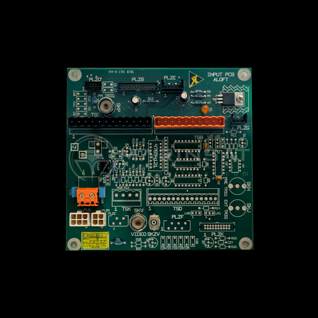
A radar PCB functions as both an electrical interconnect platform and an RF transmission structure.
Advanced radar PCB designs often use:
- Microstrip structures
- Stripline structures
- Grounded Coplanar Waveguide (GCPW)
to achieve stable RF performance.
Key Design Considerations
Controlled Impedance Design
Radar systems typically require precise impedance control, commonly:
- 50Ω RF transmission lines
- Tight impedance tolerance
Proper control of:
- Trace width
- Copper thickness
- Dielectric thickness
- Reference plane spacing
helps minimize signal reflection.
Via Optimization
Improper via structures can introduce:
- Signal discontinuity
- Radiation loss
- Impedance variation
Design strategies include:
- Via stitching
- Optimized transition structures
- Reduced via parasitic effects
Antenna Integration
Modern radar modules increasingly integrate antennas directly into the PCB structure.
Benefits include:
- Reduced module size
- Shorter RF paths
- Improved signal consistency
PCB antenna structures require precise control of:
- Layer alignment
- Material properties
- Manufacturing tolerances
RF Simulation and Verification Before Manufacturing
Due to the complexity of millimeter-wave signals, simulation plays an essential role before PCB fabrication.
Engineering analysis may include:
Electromagnetic Simulation
Tools such as:
- HFSS
- CST
are used to evaluate:
- Field distribution
- Antenna performance
- Coupling behavior
- S-parameters
Signal Integrity Analysis
Used to optimize:
- Transmission loss
- Return loss
- Phase consistency
Stackup Simulation
Ensures:
- Accurate impedance performance
- Stable propagation delay
- Manufacturable layer structures
Simulation-driven design reduces prototype iterations and improves production readiness.
Manufacturing Requirements for Automotive Radar PCBs
Automotive radar PCBs must maintain stable performance under:
- Temperature cycling
- Mechanical vibration
- Long operating periods
- Electromagnetic interference
Reliable manufacturing requires:
Precision Fabrication
Including:
- Controlled dielectric thickness
- Accurate layer registration
- Smooth copper surface treatment
- Stable lamination processes
RF Performance Verification
Quality validation may include:
- Impedance testing
- TDR analysis
- Electrical testing
- RF parameter verification
Automotive Quality Control
Automotive radar PCB manufacturing typically requires:
- IPC Class 3 production standards
- ISO 9001 quality management
- IATF 16949 automotive quality systems
Advanced inspection methods include:
- AOI inspection
- X-ray inspection
- Electrical testing
- Process traceability
Applications of Automotive Radar PCBs
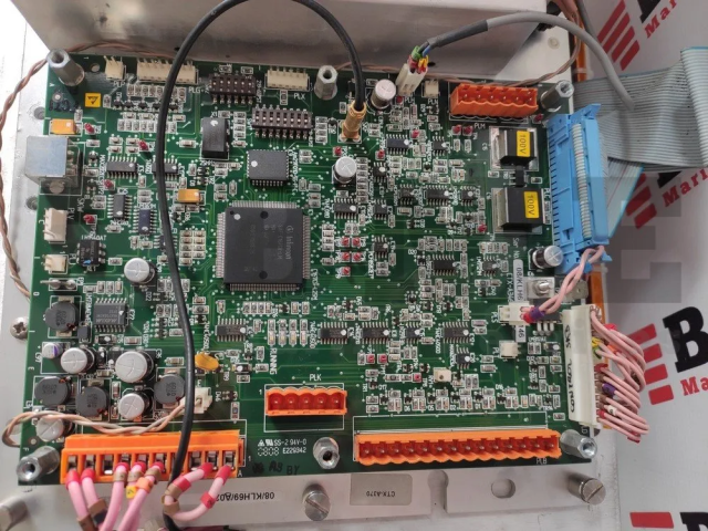
Automotive radar PCBs are widely used in:
Long-Range 77 GHz Radar
Applications:
- Highway driving assistance
- Adaptive cruise control
- Collision avoidance systems
Short-Range 79 GHz Radar
Applications:
- Blind spot detection
- Parking assistance
- Surround monitoring
24 GHz Radar Systems
Applications:
- Entry-level ADAS
- Corner radar modules
Beyond Automotive Applications
High-frequency radar PCB technology is also expanding into:
- Industrial automation
- UAV systems
- Robotics
- Intelligent transportation systems
Future Trends in Automotive Radar PCB Technology
Higher Frequency Operation
Future radar systems are moving toward:
- Higher bandwidth
- Improved resolution
- More advanced sensing capabilities
Smaller and More Integrated Modules
Radar PCBs will continue evolving toward:
- HDI structures
- Antenna-in-PCB solutions
- Compact RF integration
Higher Reliability Requirements
Future autonomous vehicles will require radar electronics with:
- Improved signal stability
- Longer operating lifetime
- Higher manufacturing consistency
Conclusion
Automotive Radar PCB technology represents the intersection of RF engineering, material science, and advanced PCB manufacturing.
As vehicles move toward higher levels of automation, radar performance increasingly depends on the precision of the PCB platform supporting the RF system.
Through advanced material selection, controlled impedance design, RF simulation, and precision manufacturing processes, KKPCB provides reliable PCB solutions for automotive radar applications — helping engineers achieve stable signal transmission, improved radar accuracy, and long-term system reliability.
