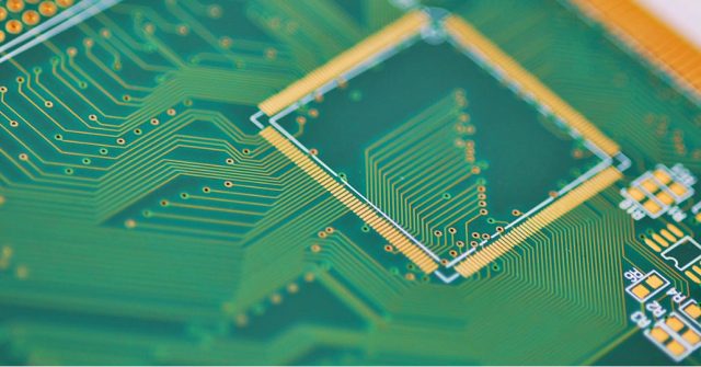
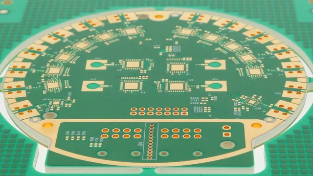
High-frequency printed circuit boards (PCBs) are critical for applications requiring precise radio frequency (RF) signal transmission, minimal signal loss, and high thermal reliability. Selecting the correct PCB material is essential to maintain signal integrity, reduce electromagnetic interference (EMI), and ensure long-term mechanical and thermal stability.
1. What Defines a High-Frequency PCB?
High-frequency PCBs are specifically designed to handle signals in the RF and microwave ranges, typically from 1 GHz to 40 GHz or higher. Unlike standard FR4 boards, these PCBs require:
-
Low dielectric constant (Dk): Ensures consistent signal speed and impedance control.
-
Low dissipation factor (Df): Minimizes signal loss, critical for high-frequency data transmission.
-
Stable coefficient of thermal expansion (CTE): Reduces mechanical stress during thermal cycling, particularly in multilayer stackups.
-
Controlled z-axis expansion: Ensures reliable plated through-hole (PTH) connections.
Applications demanding high-frequency PCBs include:
-
Wireless communications (cellular, Wi-Fi, GPS, 5G infrastructure)
-
Radar and aerospace electronics
-
Satellite communications and RF power amplifiers
-
Medical electronics for diagnostics and monitoring
2. Key Material Considerations
When designing high-frequency PCBs, engineers must evaluate electrical, thermal, and mechanical properties of the substrate.
Electrical Properties
-
Dielectric Constant (Dk): Determines the signal propagation speed and impedance. Stable Dk is crucial across the operating frequency range.
-
Dissipation Factor (Df): Low Df reduces power loss and prevents signal degradation.
-
Volume and Surface Resistivity: High resistivity prevents leakage current and EMI.
-
Dielectric Strength: Ensures the board can withstand high voltages without breakdown.
Thermal Properties
-
Glass Transition Temperature (Tg): Materials must withstand reflow soldering and operational heating; typically >170°C for FR4 and >200°C for high-performance RF materials.
-
Decomposition Temperature (Td): Ensures material stability at extreme temperatures.
-
Thermal Conductivity: Affects heat dissipation for high-power RF components.
-
Coefficient of Thermal Expansion (CTE): Must be compatible with copper and other layers to prevent delamination.
Mechanical Properties
-
Flexural Strength & Peel Strength: Maintain structural integrity under mechanical stress and during multilayer lamination.
-
Dimensional Stability: Critical for accurate impedance control and multilayer alignment.
-
Flammability Rating: UL 94 V-0 is standard for safety compliance.
3. Common High-Frequency PCB Materials
Rogers
-
Material: PTFE-based 4000 series (RO4003, RO4350B)
-
Features: Low Dk (~3.48), low Df (~0.0037 at 10 GHz), stable at high temperatures, low z-axis expansion, compatible with lead-free soldering.
-
Applications: Microwave circuits, 5G modules, base station amplifiers.
Isola
-
Material: Tachyon 100G, I-Tera MT40, Terragreen 400G, Astra MT77
-
Features: High-speed digital signal capability, low loss, thermal stability, excellent processability.
-
Applications: Multilayer PCBs, high-speed digital networks, aerospace electronics.
Panasonic
-
Material: Megtron series (Meg6, Meg7, Meg8)
-
Features: Very low loss, high Tg, excellent dimensional stability.
-
Applications: High-speed backplanes, server and networking PCBs, low-latency RF designs.
Other Options
-
Taconic, Arlon: For specialized RF/microwave applications, offering low Dk/Df and high thermal reliability.
4. Practical Guidelines for High-Frequency PCB Design
-
Stack-up Planning: Use materials with matched CTE for multilayer designs to prevent warping.
-
Impedance Control: Select materials with stable Dk across frequency range; verify with simulation tools.
-
Lead-Free Assembly: Ensure Tg and Td exceed solder reflow temperatures (>260°C for lead-free).
-
Thermal Management: For high-power RF applications, consider copper-inserted or thermally conductive laminates.
-
Supplier Collaboration: Leverage manufacturer datasheets and engineering support for stack-up optimization and material selection.
5. Summary
High-frequency PCB design requires careful material selection to maintain signal integrity, thermal stability, and mechanical reliability. Trusted high-performance laminates from Rogers, Isola, and Panasonic provide a balance of low Dk, low Df, high Tg, and mechanical strength. By understanding electrical, thermal, and mechanical properties, engineers can design high-frequency PCBs suitable for wireless communications, radar, satellite systems, and medical electronics.


