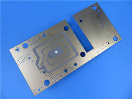
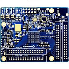
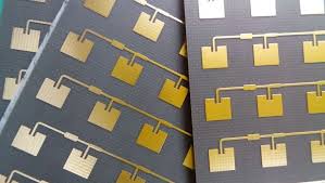
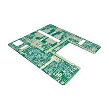
RF-35 PCB laminates operate in a class where dielectric precision directly shapes RF linearity, bandwidth uniformity, and system-level efficiency. Modern wireless products—Wi-Fi 6/7 modules, IoT gateways, sub-6 GHz links, and microwave-band transceivers—depend on stable Dk/Df behavior to maintain predictable impedance and low insertion loss. RF-35 offers a low-loss dielectric platform designed for controlled RF propagation, providing a balanced cost-performance point between PTFE-class laminates and standard hydrocarbon materials.
This article evaluates RF-35 PCB materials through engineering analysis, covering electromagnetic modeling, stackup optimization, EMI constraints, thermal loading, and real-world reliability challenges.
Core Engineering Challenges

Engineers deploying RF-35 PCB substrates typically encounter several practical obstacles:
RF propagation is affected by dielectric fluctuation under temperature cycles, which shifts impedance and increases mismatch loss.
Microwave traces in the 1–6 GHz range experience insertion-loss growth when conductor roughness, resin-glass interaction, and laminate consistency are not tightly controlled.
Cross-talk and EMI coupling worsen in multilayer RF PCB designs if the grounding architecture and return-path structure are not optimized.
High-frequency stability degrades when resonant modes are excited due to stackup asymmetry, inconsistent copper distribution, or insufficient via-fence density.
These issues define the core engineering space where RF-35 PCB implementation must be precise, validated, and simulation-driven.
Material Science & Dielectric Performance

RF-35 PCB laminate uses a ceramic-filled hydrocarbon system that improves high-frequency behavior compared with FR-4 while avoiding the processing complexity of PTFE.
The dielectric structure supports low-loss transmission, stable phase response, and predictable impedance—critical for high-density RF PCB environments.
Material Parameter Table — RF-35 PCB
| Parameter | Typical Value | Engineering Impact |
|---|---|---|
| Dielectric Constant (Dk @ 10 GHz) | 3.5 | Controls line impedance and phase stability |
| Dissipation Factor (Df @ 10 GHz) | 0.0018 | Directly reduces insertion loss for microwave traces |
| Thermal Conductivity | 0.45 W/m·K | Supports better heat spreading than FR-4 |
| Glass Transition Temperature (Tg) | > 150°C | Ensures thermal stability under RF power load |
| Peel Strength | 1.0 N/mm | Influences reliability of fine-line circuits |
| Water Absorption | < 0.1% | Maintains dielectric stability in humid environments |
RF-35’s Dk/Df stability enables RF PCB structures—filters, matching networks, antenna feeds, couplers—to maintain consistent amplitude and phase alignment across temperature, humidity, and long-term reliability conditions.
KKPCB Case Study — RF-35 PCB for Wi-Fi 6E/7 Front-End Modules

Customer Background
A client developing tri-band Wi-Fi 6E/7 modules required a low-loss RF PCB to handle 2.4 GHz, 5 GHz, and 6 GHz wideband operations.
They needed predictable impedance, controlled dielectric performance, and stable antenna feed structures to minimize phase error across high-density routing.
Engineering Pain Points
• Impedance instability due to stackup asymmetry
• Excess insertion loss at 6 GHz
• EMI leakage between RF lanes and digital baseband signals
• Temperature-induced drift under 0–105°C operation
KKPCB Engineering Approach
KKPCB adopted an RF-35 based stackup and introduced:
• Ceramic-filled RF-35 dielectric layers designed for low-loss and stable Dk
• HFSS-driven impedance tuning for CPWG and microstrip structures
• ADS harmonic analysis for front-end linearity stability
• Dense via-fence isolation to control EMI return paths
• Controlled copper roughness to lower conductor loss
Case Study Measurement Results
| Test Item | Target | RF-35 Result | Notes |
|---|---|---|---|
| Insertion Loss @ 6 GHz | < 0.45 dB/in | 0.32 dB/in | RF-35 low-loss dielectric advantage |
| Phase Variation (0–105°C) | < 4° | 2.1° | Excellent thermal stability |
| EMI Coupling | < –48 dB | –53 dB | Improved via-fence return isolation |
| Impedance Variation | ±7% | ±3% | HFSS-optimized CPWG geometry |
RF-35 delivered superior dielectric stability and lower microwave loss compared with FR-4-based or generic hydrocarbon systems.
Stackup Design & RF Implementation
RF PCB stackup design for RF-35 requires controlled impedance environments and minimized parasitic effects.
Example RF-35 PCB Stackup Table
| Layer | Material | Thickness | Application |
|---|---|---|---|
| L1 | Copper 1 oz | — | RF microstrip, antenna feed |
| Prepreg | RF-35 | 0.1 mm | Controlled dielectric zone |
| L2 | Copper 1 oz | — | Ground reference plane |
| Core | RF-35 | 0.5 mm | Structural dielectric layer |
| L3 | Copper 1 oz | — | Digital logic region |
| Prepreg | FR-type low-loss | 0.12 mm | Mechanical bonding |
| L4 | Copper 1 oz | — | Power and grounding |
Key RF Engineering Measures

• CPWG topology selected for wideband impedance stability
• Shielding vias placed every 1 mm to suppress leakage modes
• Copper roughness controlled <1.8 µm to reduce conductor loss
• HFSS eigenmode simulation performed for cavity-mode suppression
• ADS and TDR validated impedance uniformity and reflection control
This architecture maximizes RF-35’s dielectric advantages while providing isolation from digital switching noise.
Environmental & Reliability Validation
RF-35 PCB reliability must be verified under combined thermal, moisture, and vibration stresses.
Reliability Test Table
| Test | Condition | Result | Interpretation |
|---|---|---|---|
| Thermal Cycling | –40 to 125°C, 500 cycles | Pass | No Dk drift, no delamination |
| 85°C / 85% RH | 168 hours | Pass | Dielectric absorption minimal |
| Vibration | 10–2000 Hz | Pass | No via barrel cracking |
| Solder Reflow | 3× @ 260°C | Pass | Laminate and copper adhesion stable |
RF-35’s ceramic-reinforced structure maintains high-frequency performance even in demanding RF system environments.
Engineering Summary & Contact
RF-35 PCB laminates provide a strong balance of dielectric stability, low insertion loss, and thermal endurance for modern wireless applications. For systems operating from 1 to 12 GHz—antenna modules, microwave radios, Wi-Fi 7 front ends, IoT gateways, RF amplifiers—RF-35 delivers the controlled Dk/Df performance needed for stable RF behavior and consistent impedance.
KKPCB’s advanced stackup engineering, HFSS/ADS modeling flow, and full reliability validation ensure RF-35 PCB builds can achieve predictable, repeatable, and production-ready RF performance.

