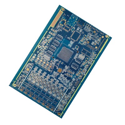
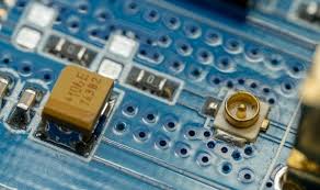
Automotive ADAS radar systems are now operating at higher frequencies, tighter channel spacing, and more aggressive signal-processing thresholds than ever. Under these conditions, the performance of an Impedance Controlled PCB becomes a dominant factor shaping radar detection accuracy, phase stability, and immunity to signal degradation. Engineering teams focusing on 77–79 GHz radar modules increasingly recognize that differential pair accuracy, crosstalk control, and stable impedance performance across multilayer RF stacks directly determine real-world radar resolution and target separation.
Using advanced Impedance Controlled PCB laminates, ADAS radar units gain a material and structural advantage: predictable differential impedance, minimized skew, and suppressed mode conversion across all high-frequency transmission lines. Unlike generic FR-4, these RF-engineered laminates maintain consistent dielectric constant (Dk) and dissipation factor (Df) across temperature and frequency, enabling wideband phase consistency essential for FMCW radar and digital preprocessing pipelines.
1. High-Frequency Impedance Control for Precision Differential Signaling

In 5th-generation ADAS radar platforms, the accuracy of differential pairs determines how well the radar front end preserves phase integrity between TX and RX channels. Even marginal impedance drift can introduce amplitude imbalance, timing mismatch, or sideband artifacts.
Advanced Impedance Controlled PCB substrates strengthen this foundation by delivering:
• tightly regulated Dk for sub-1% impedance tolerance
• low-loss dielectric behavior that minimizes insertion loss across mmWave bands
• uniform copper-dielectric interfaces that stabilize impedance under thermal cycling
• predictable etch profiles that maintain microstrip and stripline geometries at scale
Through stable impedance environments, ADAS differential pairs maintain accurate rise times, balanced propagation speeds, and extremely low skew—conditions required for high-resolution radar chirps and precise angle-of-arrival calculations.
2. Material-Driven Crosstalk Reduction for Dense Radar Architectures
Modern radar units stack multiple transmit and receive channels on compact PCB footprints. This architecture forces differential pairs, LO traces, and digital control lines into tight routes. Without crosstalk suppression engineered at the material level, high-frequency energy couples into adjacent lines and destabilizes the radar’s internal signal map.
RF-grade Impedance Controlled PCB laminates limit crosstalk through:
• lower dielectric constant variation that reduces field leakage
• optimized glass weave and resin systems that minimize fiber-induced skew
• consistent line-to-line isolation driven by predictable EM field confinement
• reduced parasitic coupling created by homogeneous dielectric domains
By stabilizing electromagnetic fields inside each transmission path, the PCB substrate prevents unwanted coupling between RF differential pairs, ensures cleaner harmonic behavior, and enhances radar detection reliability under multi-target, high-clutter scenarios.
3. Maintaining Phase Consistency Under Harsh Automotive Conditions

Automotive radar PCBs face extreme thermal cycling, moisture exposure, and mechanical stress. These conditions change the electrical behavior of generic substrates, producing impedance drift, phase distortion, and increased insertion loss.
High-performance Impedance Controlled PCB laminates eliminate these risks by providing:
• heat-resistant resin systems that maintain dielectric stability
• low-moisture absorption to protect Dk/Df performance
• oxidation-resistant copper foils for stable conductor roughness
• multilayer stackups optimized for 77 GHz radar phase alignment
The result is long-term phase consistency across every radar cycle—even after thousands of hours of vehicle operation. This stability directly supports more reliable range estimation, Doppler tracking, and object classification in advanced ADAS algorithms.
4. System-Level Benefits in ADAS Radar Units

When an ADAS radar platform is built on a properly engineered Impedance Controlled PCB, the entire signal chain—from RF front end to processor—gains quantifiable performance improvements:
• lower insertion loss throughout mmWave transmission paths
• reduced differential-to-common-mode conversion
• stronger immunity to EMI and substrate noise
• sharper radar beamforming accuracy and improved angular resolution
• more stable output under wide temperature gradients and vibration
These benefits collectively enhance the operational reliability of radar-based emergency braking, lane-keeping assist, blind-spot monitoring, and collision-avoidance systems.
Conclusion
A modern ADAS radar unit cannot reach full performance potential without a precisely engineered Impedance Controlled PCB foundation. Through enhanced differential pair accuracy, minimized crosstalk, and high-stability dielectric structures, these PCBs unlock the phase consistency, low insertion loss, and signal integrity required for next-generation automotive sensing. As radar frequency bands widen and processing demands intensify, the role of the Impedance Controlled PCB laminate becomes even more central to achieving stable, high-resolution detection in real-world driving environments.

