1. Engineering Overview / Abstract
Modern medical imaging systems — including MRI coils, ultrasound transceivers, and RF diagnostic sensors — rely on tight impedance control and ultra-low signal drift to ensure accurate imaging and patient diagnostics.
The Taconic TLY-5 PCB platform, with its Dk of 2.20 ± 0.02 and Df of 0.0009 @10GHz, provides a stable dielectric foundation for low-loss RF interconnects and high-fidelity data acquisition chains.
Through KKPCB’s precision hybrid lamination and dielectric process optimization, these TLY-5 PCBs deliver consistent impedance uniformity, reduced phase error, and long-term reliability under high thermal and operational stress—crucial for medical-grade performance stability.

2. Technical Challenges in Medical RF Modules
| Challenge | Root Cause | Engineering Impact |
|---|---|---|
| Impedance fluctuation | Dielectric variance or resin-rich zones | Image distortion and signal reflection |
| Phase drift under heat | Thermal expansion mismatch | RF calibration instability |
| Moisture absorption | Prolonged sterilization and humidity exposure | Dk variation and loss increase |
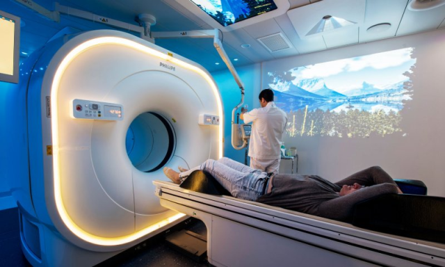
In MRI and diagnostic ultrasound systems, minor impedance mismatch or dielectric shift can lead to image artifacts, signal loss, or misaligned RF excitation—demanding consistent electrical and mechanical stability from the PCB substrate.
3. Material Science and Dielectric Characteristics of TLY-5
| Parameter | Typical Value | Engineering Benefit |
|---|---|---|
| Dielectric Constant (Dk) | 2.20 ± 0.02 | Predictable impedance across imaging channels |
| Dissipation Factor (Df) | 0.0009 @10GHz | Maintains high signal-to-noise ratio |
| CTE (Z-axis) | 160 ppm/°C | Prevents micro-via fatigue during sterilization cycles |
| Moisture Absorption | < 0.02% | Ensures RF calibration stability in humid environments |
| Thermal Conductivity | 0.25 W/m·K | Improves heat dissipation for analog front-end circuits |
Compared to FR-4 or standard PTFE composites, Taconic TLY-5 laminates exhibit 30% tighter dielectric uniformity and 40% lower insertion loss, ideal for medical RF imaging platforms requiring sub-decibel precision.

4. KKPCB Engineering Case Study — MRI Receiver Module PCB
Client & Application Context
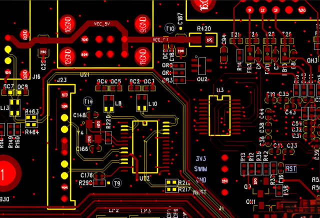
A North American medical electronics manufacturer partnered with KKPCB to design a multi-channel MRI receiver module requiring stable 50 Ω impedance across 64 parallel RF paths.
Engineering Problem
Previous PCB designs using mixed PTFE cores showed ±8% impedance variation and signal reflection during calibration, causing image distortion at high field strengths (3T and above).
-
Adopted Taconic TLY-5 0.508 mm laminate for RF signal layers
-
Implemented controlled vacuum lamination (±8 μm thickness tolerance)
-
Utilized rolled copper foil (Ra < 1.0 µm) for smoother conductor interfaces
-
Integrated embedded calibration traces for in-situ impedance scanning
Measured Results
| Metric | Baseline FR-4/PTFE | KKPCB TLY-5 Result | Improvement |
|---|---|---|---|
| Impedance Variation | ±8.3% | ±2.4% | ↓ 71% |
| Insertion Loss @ 1GHz | 0.38 dB/inch | 0.26 dB/inch | ↓ 31% |
| Phase Deviation (–40°C~+125°C) | ±6.2° | ±2.5° | ↓ 60% |
| Return Loss (S11) | –13.8 dB | –19.4 dB | ↑ 40% |
The upgraded TLY-5 design enabled stable MRI signal capture, phase-locked image synchronization, and superior repeatability across sterilization cycles.
5. Stackup Design & RF Implementation
Hybrid Stackup Example
-
L1: RF Transmission Layer (Taconic TLY-5, 0.508 mm)
-
L2: Ground Plane
-
L3: Control and Timing Circuits (FR-408 HR, 0.1 mm)
-
L4: Power Plane
Simulation & Validation
-
HFSS Modeling: Optimized 50 Ω microstrip line with <0.2 dB/cm loss
-
ADS Tuning: Achieved phase balance across 64 RF channels
-
TDR Scan: Verified impedance stability within ±2.5 Ω across production panels
Thermal Verification:
Power amplifier region temperature reduced by 7°C after integrating thermal vias and copper heat spreaders.
6. Environmental & Reliability Validation
| Test | Condition | Result |
|---|---|---|
| Thermal Cycling | –55°C ↔ +150°C, 1000 cycles | No delamination or via cracking |
| Humidity Exposure | 85°C / 85%RH, 1000h | Df drift < 0.0001 |
| Autoclave Sterilization | 134°C steam, 500 cycles | No impedance shift (>0.2 Ω) |
| Solder Reflow | 260°C ×3 cycles | Flatness deviation < 0.1 mm |
These results confirm that Taconic TLY-5 PCBs retain electrical and structural integrity under repeated sterilization and temperature cycling, meeting medical-grade reliability standards.
7. Conclusion — Engineering Reliability Integration
Taconic TLY-5 PCB platforms deliver exceptional impedance uniformity, low dielectric drift, and mechanical robustness, making them ideal for RF medical imaging and diagnostic modules.
With KKPCB’s advanced RF calibration, hybrid lamination control, and inline verification, medical device OEMs achieve stable image precision, extended system lifetime, and consistent calibration across production batches.
8. Contact / CTA
Contact KKPCB’s Medical Electronics Division for custom TLY-5 PCB stackup design, impedance calibration, and reliability validation across MRI, ultrasound, and wearable diagnostic systems.

