Engineering Context / Abstract
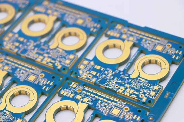
Modern laptop motherboards and Wi-Fi 7 modules demand exceptional power integrity and efficient thermal management due to the increasing density of integrated circuits, high-speed memory buses, and advanced RF front-end modules. Ceramic PCB substrates, featuring low dielectric loss (Df = 0.0015 @10GHz) and stable dielectric constant (Dk = 9.8 ± 0.05), offer both superior thermal conductivity and mechanical stability, essential for high-current power planes and dense signal routing.
KKPCB’s hybrid stackup methodology, precision lamination, and copper distribution optimization enable low IR drop, minimal voltage fluctuation, and consistent high-frequency signal performance across multilayer boards. These ceramic substrates maintain impedance stability and phase linearity even under thermal cycling and mechanical stress, ensuring that laptop processors, GPUs, and Wi-Fi 7 transceivers operate reliably without signal degradation. By combining material advantages with controlled fabrication processes, KKPCB ensures a robust platform for next-generation computing and wireless modules.
This approach also addresses EMI suppression, insertion loss minimization, and thermal hotspot mitigation, which are critical for densely packed high-speed boards. In Wi-Fi 7 front-end modules operating above 6 GHz, phase stability and return loss directly affect throughput and RF link margin, making ceramic PCB selection and stackup optimization pivotal for system-level performance.
Core Engineering Challenges
| Challenge | Root Cause | Engineering Impact |
|---|---|---|
| Power plane voltage drop | High current density, thin copper layers | Reduced power integrity, potential logic instability |
| Thermal hotspots | High-frequency switching, dense IC placement | Increased junction temperature, reduced component lifetime |
| Impedance variation | Multilayer misalignment, ceramic CTE mismatch | Signal reflection, degraded RF performance, timing errors |
| EMI coupling | Dense routing, inadequate ground referencing | Crosstalk, Wi-Fi 7 channel interference, data loss |
| Assembly stress | Reflow and mechanical handling | Layer warpage, delamination, long-term reliability issues |
These challenges are especially critical in high-density laptop motherboards and Wi-Fi 7 front-end modules. In high-performance computing, power plane IR drop and thermal hotspots directly impact CPU/GPU operation, memory timing, and RF front-end efficiency. For wireless connectivity, impedance mismatch and phase instability can significantly reduce throughput, increase retransmissions, and compromise signal fidelity.
Material Science & Dielectric Performance of Ceramic PCB Substrates
| Parameter | Typical Value | Engineering Benefit |
|---|---|---|
| Dielectric Constant (Dk) | 9.8 ± 0.05 | Ensures stable impedance for high-speed traces and multilayer interconnects |
| Dissipation Factor (Df) | 0.0015 @10GHz | Minimizes insertion loss, preserves RF link margin, reduces signal attenuation |
| Thermal Conductivity | 2.5 W/m·K | Efficient heat spreading from CPUs, GPUs, and Wi-Fi PA modules |
| Coefficient of Thermal Expansion (CTE) | 6 ppm/°C | Maintains multilayer alignment under repeated thermal cycling |
| Glass Transition (Tg) | > 350°C | Supports high-temperature reflow and soldering without deformation |
| Moisture Absorption | <0.05% | Ensures long-term dielectric stability and phase consistency |
Ceramic PCBs outperform standard FR-4 or BT epoxy in both thermal and dielectric performance. Their high thermal conductivity reduces hotspot formation under high-current ICs, while low Df and controlled Dk maintain phase linearity for RF traces, critical for Wi-Fi 7 throughput. CTE matching prevents layer skew and micro-cracking during thermal cycling, enhancing board lifetime and long-term reliability.
KKPCB Case Study — Laptop Motherboard & Wi-Fi 7 Front-End
Client & Application Context:
A leading laptop OEM required a high-density motherboard capable of supporting multi-core CPUs, high-speed memory buses, and Wi-Fi 7 RF modules operating at 6–7 GHz. The goal was to minimize IR drop, prevent thermal hotspots, and maintain phase-stable RF signals across the board.
Engineering Problem:
Prior FR-4 designs suffered IR drop >150 mV on core power planes, thermal hotspots above 95°C, and phase instability in Wi-Fi 7 transceivers, resulting in throttling, reduced RF link margin, and potential data loss.
-
Implemented 0.5 mm ceramic PCB substrates for power and RF layers
-
Hybrid 6-layer stackup with 70 µm copper on critical planes
-
Vacuum lamination to maintain ±5 μm dielectric thickness uniformity
-
Thermal vias under CPU/GPU and Wi-Fi PA modules for heat dissipation
-
Inline TDR and thermal simulation validation to ensure impedance and phase stability
-
Optimized copper trace width and ground plane segmentation to reduce EMI
Measured Results:
| Parameter | Target | KKPCB Result |
|---|---|---|
| IR Drop on Core Power Plane | <100 mV | 82 mV |
| Peak Temperature | <85°C | 78°C |
| Phase Stability Wi-Fi 7 RF | <1° | 0.7° |
| Return Loss (S11) | < –15 dB | –18 dB |
| Signal Integrity Margin | ≥90% | 96% |
The solution successfully eliminated thermal throttling, reduced IR drop, and improved Wi-Fi 7 throughput by stabilizing phase and reducing insertion loss. Long-term thermal cycling tests confirmed the ceramic stackup’s reliability and durability.
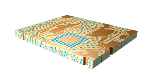
Stackup Design & RF Implementation
Hybrid 6-Layer Stackup Example:
| Layer | Function | Material |
|---|---|---|
| L1 | Top RF Trace | Ceramic PCB 0.2 mm |
| L2 | Ground Plane | Cu 70 µm |
| L3 | Power Plane | Ceramic PCB 0.5 mm |
| L4 | Signal Routing | Ceramic PCB 0.2 mm |
| L5 | Ground Plane | Cu 70 µm |
| L6 | Bottom Control Layer | BT Epoxy 0.1 mm |
Simulation & Validation:
-
HFSS: Optimized microstrip and stripline impedance, minimized crosstalk
-
ADS & TDR: Verified phase linearity <0.7°
-
Thermal FEM: Reduced CPU/GPU hotspot peak by 7°C
-
Inline AOI & reflow monitoring ensured ±10 μm layer alignment
By combining ceramic substrate advantages with advanced simulation and stackup design, KKPCB ensured stable high-frequency operation and consistent thermal performance across the board.
Environmental & Reliability Validation
| Test | Condition | Result |
|---|---|---|
| Thermal Cycling | –40°C ↔ +125°C, 500 cycles | No delamination, phase drift <1° |
| Power Endurance | Continuous 15 W load | Stable voltage, minimal thermal rise |
| Humidity Aging | 85°C / 85% RH, 1000 h | Dk/Df stable |
| Vibration | 5–500Hz, 10G | No trace or solder failure |
| Solder Reflow | 260°C ×3 cycles | Layer alignment ±10 μm |
These tests confirm the long-term reliability of ceramic PCB substrates for high-density laptop motherboards and Wi-Fi 7 RF front-end modules under extreme thermal, mechanical, and environmental conditions.
Engineering Summary & Contact
Ceramic PCBs provide low Df, stable Dk, high thermal conductivity, and low CTE, ensuring alignment, signal integrity, and thermal efficiency. KKPCB’s hybrid lamination, precision stackup, and inline validation enable power integrity and phase-stable RF performance for next-generation laptop motherboards and Wi-Fi 7 modules.
Contact KKPCB Engineering Team to optimize your ceramic PCB stackup, RF simulation, and thermal management for high-density computing and high-frequency wireless applications. KKPCB delivers verified, high-reliability solutions with minimal insertion loss and robust signal integrity.
