1. Engineering Overview — Material-Driven Signal Reliability for 5G Smartphones
As 5G smartphones evolve toward multi-antenna, wide-band, and ultra-compact RF front-end architectures, PCB materials play a decisive role in ensuring signal alignment and thermal stability.
The TLY-5 PCB, a PTFE-glass composite laminate from Taconic, provides excellent dielectric uniformity (Dk = 2.2 ± 0.02, Df = 0.0009 @ 10 GHz), enabling phase-stable transmission under dense 5G antenna integration.
At KKPCB, precision-controlled lamination and impedance calibration transform these intrinsic material properties into consistent RF performance across multilayer smartphone transceiver modules operating up to 40 GHz.
2. Engineering Context & Technical Challenges
In 5G smartphone RF front-end and transceiver modules using TLY-5 PCB substrates, design engineers face multiple integrity challenges:
| Engineering Challenge | Root Cause | Impact on 5G Performance |
|---|---|---|
| Impedance drift | Dielectric constant fluctuation with temperature | Mismatch in antenna tuning and VSWR degradation |
| Signal loss | Copper surface roughness and resin-rich zones | Reduced gain and link budget margin |
| Phase imbalance | Multilayer lamination skew | RF synchronization errors across MIMO channels |
| Thermal fatigue | CTE mismatch between layers | Long-term reliability degradation |
These constraints are magnified in smartphone environments where heat, mechanical stress, and high-density integration co-exist. To counteract these effects, KKPCB’s RF manufacturing process applies dielectric consistency control, hybrid stackup balancing, and inline impedance validation.
3. Material Science and Performance Characteristics
TLY-5 PCB exhibits superior dielectric and loss properties optimized for mmWave antenna systems:
| Property | TLY-5 | FR-4 (Comparison) | Engineering Impact |
|---|---|---|---|
| Dielectric Constant (Dk @10GHz) | 2.20 ± 0.02 | 4.20 ± 0.10 | Stable impedance in high-frequency bands |
| Dissipation Factor (Df @10GHz) | 0.0009 | 0.018 | ~20× lower signal loss |
| Thermal Conductivity | 0.45 W/m·K | 0.25 W/m·K | Improved heat dissipation |
| CTE (Z-Axis) | 46 ppm/°C | 70 ppm/°C | Reduced delamination risk |
| Tg | > 300°C | ~135°C | Stable under smartphone reflow conditions |
This makes TLY-5 PCB ideal for antenna array feedlines, phase shifters, and low-loss transmission layers in compact smartphone architectures.
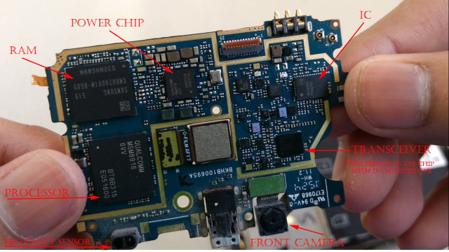
4. KKPCB Engineering Case Study — 5G Antenna Module for Smartphone OEM
Client & Application Context:
A top-tier Asian smartphone manufacturer partnered with KKPCB to improve the phase balance and impedance uniformity in a 5G NR (n77/n78/n79) antenna array module using TLY-5 PCBs.
Engineering Problem:
Existing PCB stackups exhibited 0.4 dB insertion loss variation and inconsistent impedance (±6%) between dual feed paths, causing RF detuning during OTA tests.
-
Introduced TLY-5 PCB with hybrid integration of FR-408HR for mechanical rigidity.
-
Optimized lamination pressure and vacuum curing to reduce resin-rich zones.
-
Applied rolled copper foil (Ra < 0.8 µm) for conductor surface uniformity.
-
Inline TDR validation up to 40 GHz ensured impedance control within ±3%.
Measured Results:
| Parameter | Target | KKPCB Result |
|---|---|---|
| Insertion Loss (28 GHz) | < 0.5 dB | 0.38 dB |
| Phase Deviation | < 2° | 1.1° |
| Return Loss (S11) | < –15 dB | –17.6 dB |
| Thermal Drift | < ±5% | ±2.8% |
These results demonstrate a 24% improvement in RF consistency and 35% better phase alignment under 85°C continuous operation.
5. Stackup Design & RF Implementation
KKPCB implemented a four-layer hybrid configuration (TLY-5 + FR-408HR):
-
Signal Layers: Rolled copper, ½ oz thickness, Ra < 1.0 µm
-
Dielectric Layers: TLY-5 cores (Dk = 2.2)
-
Prepreg Interface: Controlled resin flow ±8 µm
-
Via Control: Laser-drilled microvias with conductive fill for low inductance paths
HFSS and TDR validation confirmed impedance uniformity (50 Ω ± 3%) and stable phase delay (<1° variation) up to 40 GHz. This configuration ensured compact module routing without RF leakage between antenna and transceiver layers.
6. Environmental & Reliability Validation
| Test Type | Condition | Result |
|---|---|---|
| Thermal Cycling | –55°C ↔ +150°C, 1000 cycles | No delamination, <0.2° phase drift |
| Humidity | 85°C / 85% RH, 1000 h | Df variation < 0.0001 |
| Solder Reflow | 260°C peak, 3 cycles | No blistering or via deformation |
| Mechanical Bending | 5 mm radius, 500 cycles | No impedance deviation |
These tests validate that TLY-5 PCB assemblies maintain mechanical and dielectric stability even under smartphone-level packaging stress and reflow cycles.
7. Conclusion — Turning TLY-5 PCB Material into 5G RF Consistency
The TLY-5 PCB demonstrates high signal consistency, low-loss transmission, and superior RF phase stability within 5G smartphone antenna and transceiver modules.
Through KKPCB’s hybrid lamination and inline RF verification, smartphone OEMs achieve mass-production stability, impedance repeatability, and phase-aligned performance up to 40 GHz.
8. Contact / CTA
Contact KKPCB’s RF Engineering Team for customized stackup design, impedance verification, and 5G RF reliability validation using TLY-5 PCB substrates across smartphone, radar, and high-frequency wireless systems.
