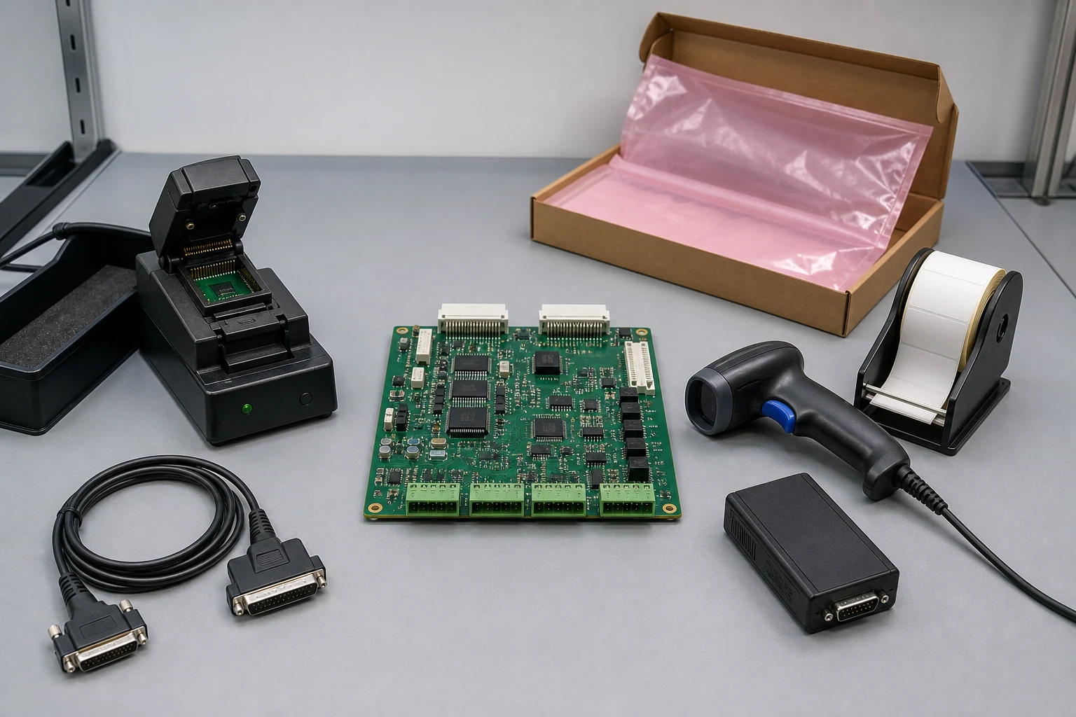
As a PCB and PCBA manufacturing partner, KKPCB supports electronic hardware production through integrated PCB manufacturing, PCB assembly services, component sourcing, and quality control.
1. Define the Safety Boundaries of an Energy Storage BMS PCBA
Before manufacturing begins, the BMS architecture and the responsibilities of each system component should be clearly defined.
An energy storage system may include:
- Battery cells and battery modules
- Cell monitoring units and battery monitoring boards
- A central BMS controller or battery management unit (BMU)
- Current and battery-pack voltage measurement circuits
- Temperature sensors and monitoring channels
- Insulation monitoring or ground-fault detection devices, where applicable
- Contactors, pre-charge circuits, and fuses
- Chargers, inverters, and auxiliary power supplies
- Communication interfaces and service connectors
These components operate within different electrical domains and perform different safety-related functions. The system design must identify isolation barriers, communication paths, and the devices responsible for controlling the flow of electrical energy.
Define the Electrical and Functional Requirements
The battery or system OEM should establish the released requirements before the design is transferred to manufacturing. These requirements typically include:
- Cell chemistry and series/parallel configuration
- Battery and pack voltage ranges
- Charging and discharging current limits
- Operating and storage temperature ranges
- Measurement accuracy and calibration requirements
- Cell balancing behavior
- Isolation requirements and communication protocols
- Power-up, shutdown, and recovery behavior
- Fault thresholds, response delays, and recovery conditions
Thresholds, filtering, hysteresis, latching behavior, and recovery rules must come from the approved system design. They should not be inferred solely from a monitoring IC datasheet.
The BMS PCBA manufacturer is responsible for building and testing the released hardware and software configuration according to the agreed requirements. The system OEM retains responsibility for the overall battery architecture, hazard analysis, system-level protection strategy, and applicable product compliance.
A functional PCBA test does not establish that the complete energy storage system is safe or certified. Board-level verification supports the broader product validation process but does not replace it.
2. Control PCB Isolation and High-Voltage Design Requirements
Isolation is an important consideration in energy storage BMS PCB assembly, particularly where low-voltage control circuits interface with high-voltage battery domains.
The PCB stack-up, spacing, slots, barriers, coatings, and voltage-domain markings must follow the approved electrical design and applicable requirements.
The required creepage distances and clearances depend on factors such as:
- Working voltage and transient voltage
- Pollution degree and environmental conditions
- Altitude
- Insulation material properties
- Applicable product standards
- The electrical architecture of the complete system
A generic voltage classification is not sufficient to establish the correct PCB layout requirements. The responsible design and compliance teams must determine the applicable criteria.
Control Critical Isolation Components
Components such as digital isolators, isolation amplifiers, optocouplers, transformers, isolated power supplies, relays, and connectors must match the released bill of materials (BOM) and approved sourcing records.
Components with similar packages are not necessarily interchangeable. They may differ in pin assignments, isolation ratings, operating limits, aging characteristics, and certification documentation.
Before approving an alternative component, the responsible teams should review its electrical performance, insulation characteristics, layout compatibility, thermal behavior, firmware implications, and compliance documentation.
Manufacturing inspection should also address:
- Solder bridges and conductive debris
- Damaged PCB slots or barriers
- Contamination around high-impedance measurement areas
- Incorrect connector installation
- Coating defects in designated isolation regions
- Rework that reduces required electrical spacing
Establish Controlled Isolation Testing
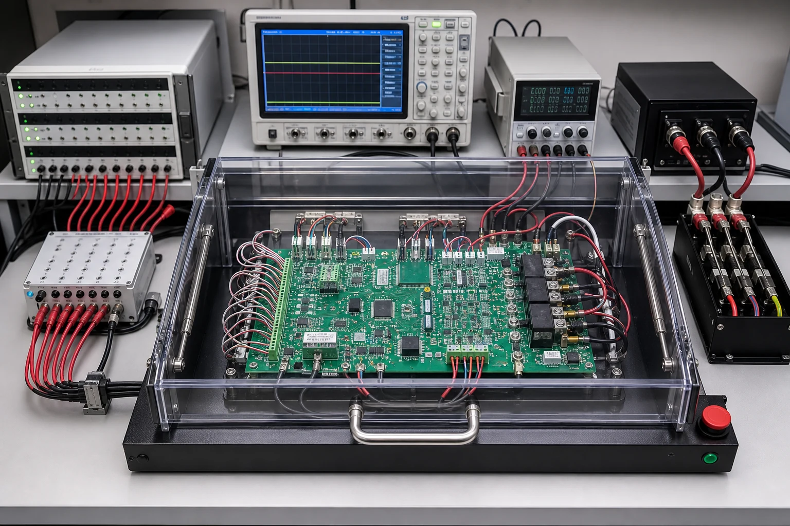
If dielectric withstand, insulation resistance, or other electrical isolation tests are required, the OEM should specify the approved test method, circuit connections, test conditions, duration, limits, discharge procedure, and acceptance criteria.
Test fixtures should incorporate appropriate guarding, interlocks, and safe discharge provisions. They must also prevent test conditions from damaging communication interfaces or unprotected circuit sections.
Do not apply a generic high-voltage test value to every BMS design. Test parameters must be derived from the approved design and applicable requirements.
3. Calibrate Battery Voltage, Current, and Temperature Channels
Accurate measurement is fundamental to BMS PCBA safety. However, a measurement value that appears reasonable does not necessarily prove that the correct physical channel has been measured.
A BMS may report an accurate voltage under test while associating it with the wrong cell number. It may also fail to identify an open sensor connection or apply an incorrect conversion factor.
Manufacturing verification should therefore cover both measurement accuracy and channel identity.
Cell Voltage Measurement
The released design should define the mapping between physical cell connections, monitoring inputs, processor data, and reported system values.
Production testing should verify:
- Channel identity and mapping
- Measurement polarity
- Offset and gain accuracy
- Numeric conversion and reported units
- Repeatability at approved test points
- Open-wire detection, where supported by the design
Where appropriate, the test plan should include representative points across the approved measurement range.
Current and Battery-Pack Voltage Measurement
Current measurement may use a shunt resistor and amplifier, a Hall-effect sensor, or another approved sensing architecture.
The manufacturing test plan should verify the relevant measurement range, direction, offset, gain, and temperature behavior. Particular attention should be paid to low-resistance connections, current-sense routing, reference paths, and calibration coefficients.
Battery-pack voltage measurement requires its own review of the divider network, isolation architecture, and ADC mapping. It should not be inferred simply by summing individual cell readings.
Temperature Monitoring
Temperature verification should identify the actual sensor type, physical location, input channel, and conversion characteristics.
Testing may use approved simulation sources or reference equipment to verify:
- Sensor-channel mapping
- Measurement range and polarity
- Conversion accuracy
- Open-circuit and short-circuit detection, where supported
- Response to defined fault conditions
The temperature of a processor is not a substitute for measuring the temperature of a battery cell, busbar, connector, or enclosure.
Establish a Measurement Uncertainty Strategy
Before pilot production, define the measurement uncertainty budget and acceptance guard bands.
Relevant factors may include source accuracy, instrument accuracy, fixture resistance and leakage, settling time, ambient temperature, software rounding, and station repeatability.
If measurements drift or fail, investigate whether the cause is the product hardware, test source, fixture contact, reference equipment, software timing, or configuration. Do not widen the acceptance limits merely to improve production yield.
4. Verify BMS Firmware and Protection Functions
BMS firmware determines how measurement data is interpreted, how system status is reported, and how defined protection responses are initiated.
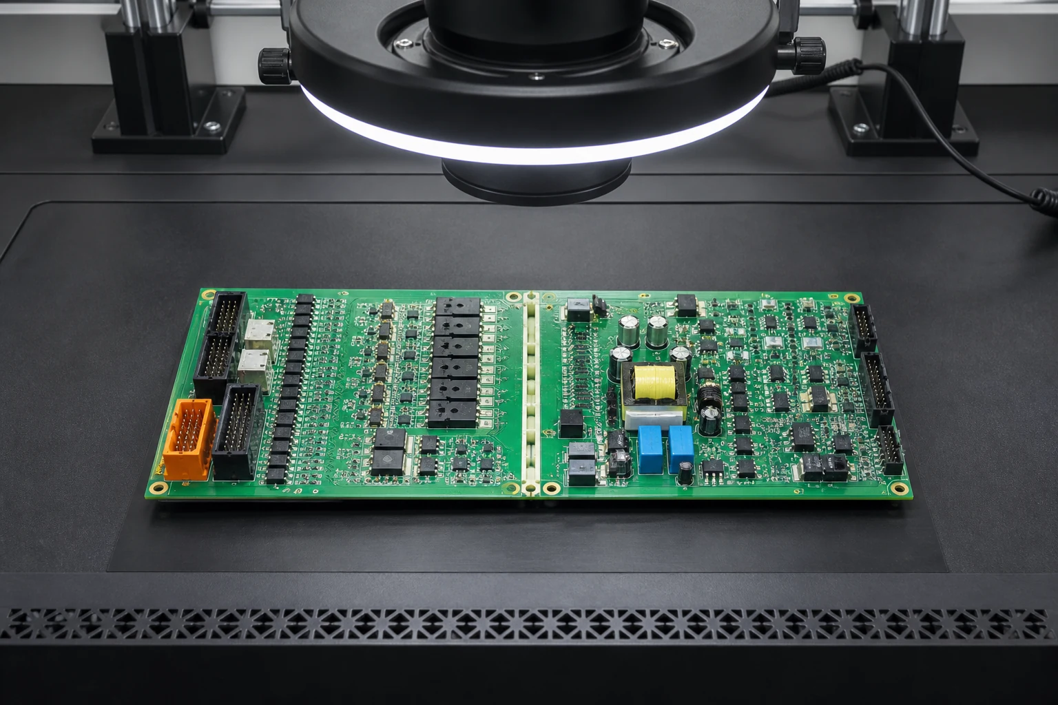
A reliable manufacturing process must ensure that each board receives the correct approved firmware and parameter configuration.
Controlled release information may include:
- Bootloader and application firmware versions
- Hardware revision
- Battery chemistry and cell configuration
- Protection thresholds and timing parameters
- Communication identifiers and settings
- Calibration coefficients
- Safety-related configuration values
- Programming authorization and verification requirements
Test Power States and Startup Behavior
Production verification should cover the applicable power-up, wake-up, sleep, shutdown, reset, and recovery behavior.
The test plan should also consider watchdog operation, reset causes, low-voltage conditions, and output states during programming or reset.
The objective is to confirm that the board follows the released design and does not enter an unintended output state during normal manufacturing operations.
Verify Protection Responses Using Controlled Fault Simulation
Where supported by the approved test architecture, simulated battery voltage, temperature, current, and communication faults can be used to verify defined protection paths.
For each applicable test, record:
- The initial board and system state
- The applied stimulus or fault condition
- The relevant threshold and response delay
- The expected status indication or output
- The observed result
- The required latching and recovery behavior
If a BMS sends a command to another controller rather than directly controlling a contactor, the test should verify the message and interface. It should not claim that the complete energy path has been disconnected unless the broader system test demonstrates that result.
Verify Communication Interfaces
Communication testing should cover the physical interfaces and message functions defined in the released design. Depending on the product, this may include CAN, RS-485, or other communication interfaces.
Tests may verify:
- Node identity and communication configuration
- Correct message values and status flags
- Fault reporting
- Command permissions
- Communication timeouts
- Connector and transceiver functionality
- Isolation behavior, where applicable
A software loopback test may bypass the physical connector, transceiver, or isolation component. Test documentation should identify exactly which physical paths have been verified and which remain to be validated during system integration.
5. Establish PCBA Traceability and Configuration Control
Traceability allows manufacturers and customers to reconstruct the manufacturing history of an individual board or controlled production batch.
For safety-relevant BMS electronics, traceability should connect hardware identity with its actual manufacturing, programming, calibration, testing, and release records.
Depending on the agreed requirements, records may include:
- Serial number or controlled batch identifier
- PCB revision and BOM configuration
- Approved component sources and relevant lot information
- Assembly process records
- Firmware and parameter versions
- Calibration coefficients and measurement results
- Test fixture and test program revisions
- Initial failures, repairs, and retest results
- Final inspection and release authorization
Preserve First-Failure Records
A successful final test should not erase the history of an earlier failure.
If an initial test fails because of a suspected contact issue, the manufacturing process should preserve the first result and record the reason for any approved retest.
Repeated channel, isolation, programming, or fixture failures should trigger investigation rather than being treated as routine events.
Make Release Decisions Auditable
A release record should identify the approved configuration, applicable test evidence, any authorized deviations, and the person or function responsible for final disposition.
Access control, data retention, backup, and record integrity should be defined according to the product’s quality requirements.
6. Manage Engineering Changes and Component Substitutions
Changes to BMS hardware or manufacturing processes can affect measurement accuracy, isolation, protection behavior, or compliance.
Changes requiring review may include:
- PCB stack-up, spacing, or material
- Battery monitoring ICs and reference components
- Isolation devices and power supplies
- Current shunts and sensing amplifiers
- Connectors, relays, and output drivers
- Temperature sensors
- Component suppliers or approved part numbers
- Soldering, cleaning, and coating processes
- Firmware, parameters, and calibration limits
- Test fixtures, programs, and acceptance criteria
The required revalidation depends on the change and its potential failure mechanisms.
Control Substitutions and Deviations
Component alternatives should be reviewed against the approved BOM and acceptance criteria before use.
Temporary substitutions, wider calibration limits, skipped tests, or manual processing should require explicit authorization. Records should identify affected serial numbers or batches, the validity period, additional verification requirements, and the closure process.
This approach helps prevent expired approvals or undocumented alternatives from remaining in production.
7. Evaluate a BMS PCBA Manufacturing Partner
Selecting a BMS PCBA manufacturer requires more than checking equipment lists or reviewing general quality certificates.
OEMs should evaluate whether the manufacturer can follow the released design, control critical components, execute the agreed test plan, maintain traceability, and communicate changes effectively.
| Evaluation Area | Key Questions |
|---|---|
| PCB Manufacturing | Can the supplier meet the released layer stack-up, material, copper, and dimensional requirements? |
| Component Sourcing | Are approved part numbers and authorized substitutions controlled? |
| SMT and Assembly | Are assembly processes and inspection methods appropriate for the design? |
| Isolation and Cleanliness | Are the required inspection and electrical test procedures documented? |
| Calibration | Can measurement channels be tested using controlled sources and defined limits? |
| Firmware Programming | Are firmware versions, parameters, and programming results traceable? |
| Functional Testing | Does the test plan cover the agreed measurement, communication, and protection paths? |
| Traceability | Can the supplier reconstruct hardware, component, firmware, calibration, and test history? |
| Change Management | Are engineering changes and deviations reviewed and approved before implementation? |
For a meaningful comparison, issue the same controlled RFQ package to each candidate supplier.
The package should define the PCB design, BOM, approved alternatives, firmware responsibilities, test coverage, traceability fields, expected volumes, delivery requirements, non-recurring engineering costs, recurring production costs, and change-notification expectations.
Suppliers should respond with documented manufacturing assumptions, design-for-manufacturing findings, proposed test coverage, traceability examples, and identified limitations.
8. Standards and System-Level Compliance
Applicable standards depend on the product, battery chemistry, application, target market, and certification pathway.
IEC 62619 addresses safety requirements for secondary lithium cells and batteries used in industrial applications, including certain stationary applications. The applicable edition and product-specific requirements must be determined by the responsible OEM and compliance team.
UL 9540 addresses energy storage systems and equipment as part of a broader system evaluation. Its relevance to a particular product depends on the product scope and intended certification pathway.
Standards applicable to the overall system should not automatically be represented as certifications of an individual PCBA.
A manufacturing supplier should support the compliance process by maintaining controlled manufacturing records, approved component information, test evidence, and change history. Any compliance claim must be supported by the applicable evaluation and authorization.
PCBA functional testing supports system validation; it does not replace battery qualification, system-level risk assessment, or required product certification.
Frequently Asked Questions
What Should an OEM Include in an Energy Storage BMS PCBA RFQ?
An RFQ should include the PCB design files, BOM, electrical architecture, battery chemistry and configuration, voltage and temperature measurement requirements, isolation requirements, communication interfaces, firmware and calibration responsibilities, production test requirements, applicable standards, traceability fields, and expected production volumes.
It should also distinguish between board-level manufacturing responsibilities and system-level validation activities.
Can a Functional BMS PCBA Test Prove That an Energy Storage System Is Safe?
No. A functional PCBA test verifies defined board-level functions under specified test conditions. Overall system safety also depends on battery cells, contactors, fuses, wiring, enclosure design, thermal management, system controls, installation, operating conditions, and the applicable risk assessment and certification process.
How Should BMS Measurement Channels Be Calibrated During Production?
Use approved, traceable electrical stimuli at defined test points. Verify channel identity, polarity, offset, gain, conversion accuracy, and acceptance limits. Record the test equipment, fixture, procedure, software revision, coefficients, and results.
Which BMS PCBA Changes Should Trigger a Customer Review?
Changes to PCB construction, isolation components, monitoring ICs, current-sensing circuits, connectors, sensors, approved component sources, manufacturing processes, firmware, calibration, test fixtures, or acceptance limits may require review.
The required revalidation should be determined by the change-control procedure, risk assessment, and applicable quality or certification requirements.
Conclusion
Reliable energy storage BMS PCBA manufacturing requires a coordinated approach to PCB fabrication, component control, assembly quality, measurement calibration, firmware configuration, functional testing, and traceability.
The most important principle is to verify the released design and its defined functions without confusing board-level test results with complete battery-system safety.
KKPCB provides integrated PCB fabrication and PCBA manufacturing services, including SMT assembly, component sourcing, and quality control.
These capabilities can support BMS developers and energy storage equipment manufacturers with prototype builds, engineering validation, and production programs according to the approved design and agreed manufacturing requirements.
Planning an energy storage BMS PCBA project?
Contact KKPCB to discuss your PCB specifications, assembly requirements, component sourcing needs, and production test plan.