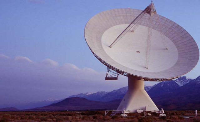
A Duroid 5880 PCB for radar module is widely recognized as one of the most reliable solutions for high-frequency and millimeter-wave radar systems. Radar modules operating at 24GHz, 60GHz, and 77GHz require ultra-low signal loss, stable dielectric properties, and precise impedance control to ensure accurate target detection and signal processing.
RT/duroid 5880 material, developed by Rogers, is specifically engineered for microwave and RF applications, making it an ideal choice for advanced radar module PCB designs.
Why Use Duroid 5880 PCB for Radar Modules
Radar systems rely on extremely high-frequency signals, where even small dielectric variations can significantly impact system performance. A Duroid 5880 PCB for radar module provides consistent electrical characteristics that help maintain signal accuracy.
Key advantages include:
-
Ultra-low dielectric constant (Dk ≈ 2.2)
-
Extremely low dissipation factor (Df ≈ 0.0009)
-
Minimal signal attenuation at mmWave frequencies
-
Excellent phase stability and repeatability
-
Superior performance compared to standard FR-4 materials
These properties make Duroid 5880 PCBs ideal for radar front-end and antenna integration.
Design Features of Duroid 5880 PCB for Radar Module
A properly designed Duroid 5880 PCB for radar module focuses on RF performance, mechanical stability, and manufacturing precision.
Controlled Impedance RF Routing
Precise control of trace width, dielectric thickness, and copper geometry ensures accurate impedance for radar signal transmission lines.
Antenna and RF Structure Integration
Duroid 5880 PCBs are commonly used to integrate patch antennas, transmission lines, and RF matching networks within compact radar modules.
Low Copper Surface Roughness
Smooth copper foils reduce conductor loss and improve high-frequency signal performance.
Manufacturing Requirements for Duroid 5880 Radar PCBs
Producing a high-quality Duroid 5880 PCB for radar module requires specialized manufacturing expertise.
Key manufacturing capabilities include:
-
Precision lamination for PTFE-based materials
-
Controlled impedance PCB processing
-
Fine line and space etching
-
Laser drilling for RF vias and microvias
-
RF-optimized surface finishes such as ENIG or immersion silver
-
TDR and impedance verification
Strict process control ensures consistency and repeatability in radar module production.
Hybrid Stack-Up Solutions
Many radar modules use hybrid PCB constructions, combining Duroid 5880 layers with high-Tg FR-4 or other RF materials. This approach balances RF performance, mechanical strength, and cost efficiency.
A professional Duroid 5880 PCB manufacturer provides engineering support to optimize hybrid stack-up design and reliability.
Applications of Duroid 5880 PCB for Radar Module
Duroid 5880 radar PCBs are widely used in:
-
Automotive radar modules (ACC, BSD, collision avoidance)
-
Aerospace and defense radar systems
-
Industrial radar sensors
-
Traffic monitoring and security radar
-
Short-range and long-range radar platforms
In all these applications, ultra-low loss PCB performance is critical for detection accuracy and system reliability.
From Prototype to Mass Production
A Duroid 5880 PCB for radar module is typically validated through prototype builds to verify RF performance, impedance accuracy, and antenna efficiency. Once confirmed, the same materials and processes are scaled to volume production, ensuring consistent radar performance across all units.
Conclusion
A Duroid 5880 PCB for radar module delivers exceptional electrical performance for high-frequency and millimeter-wave radar applications. With ultra-low dielectric loss, stable impedance characteristics, and proven reliability, Duroid 5880 remains a preferred material for advanced radar systems.
Choosing an experienced Duroid 5880 PCB manufacturer ensures accurate fabrication, reliable performance, and smooth transition from prototype to mass production in demanding radar applications.
