In radar systems, signal integrity defines system capability. Detection range, resolution, and accuracy are all directly influenced by transmission loss and phase consistency. For this reason, Duroid 5880 PCB for radar module applications has become a preferred choice where performance margins are extremely tight.
By significantly reducing dielectric loss and maintaining stable electrical behavior, Duroid 5880 enables radar modules to operate with higher precision and repeatability.
Radar Signal Loss and PCB Material Impact
Radar modules operating at microwave and millimeter-wave frequencies are highly sensitive to PCB material properties. Excessive dielectric or conductor loss can result in:
-
Reduced detection range
-
Degraded signal-to-noise ratio
-
Phase distortion affecting target localization
Using Duroid 5880 PCB for radar module designs helps preserve signal strength throughout the RF path.
Electrical Properties of Duroid 5880 Relevant to Radar Modules
Duroid 5880 is a PTFE-based laminate engineered for extreme high-frequency performance. Key characteristics include:
-
Low dielectric constant (Dk ≈ 2.2)
-
Ultra-low dissipation factor (Df ≈ 0.0009)
-
Excellent phase stability over temperature
-
Minimal moisture absorption
These properties directly support high-frequency radar signal transmission with minimal degradation.
Phase Stability and Impedance Control
Radar systems rely not only on amplitude but also on phase accuracy. Duroid 5880 PCB for radar module manufacturing emphasizes:
-
Precise impedance-controlled transmission lines
-
Consistent dielectric thickness across panels
-
Tight control of copper geometry
-
Verification through impedance and RF testing
Stable phase response improves radar resolution and object detection accuracy.
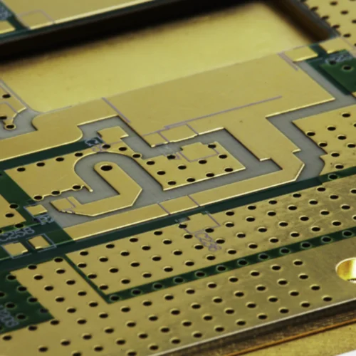
PCB Stackup Strategies for Radar Modules
Typical Duroid 5880 PCB for radar module stackups include:
-
Single-layer or double-layer antenna boards
-
Multilayer radar PCBs with dedicated ground reference planes
-
Hybrid constructions combining Duroid 5880 with FR-4 or Rogers materials
Hybrid stackups are often used to optimize mechanical strength and cost while preserving RF performance.
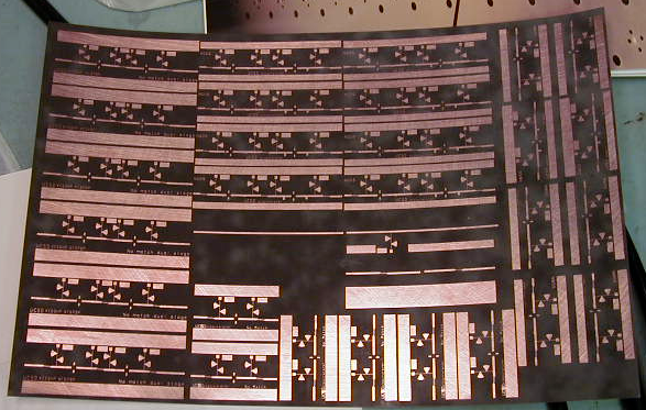
Manufacturing Challenges of Duroid 5880 Radar PCBs
Producing high-quality Duroid 5880 PCB for radar module designs requires specialized processes:
-
Controlled drilling and plating for PTFE materials
-
Fine-line etching for mmWave RF traces
-
Copper roughness management to reduce conductor loss
-
Stable lamination for multilayer alignment
These challenges demand experienced RF PCB manufacturing capability.
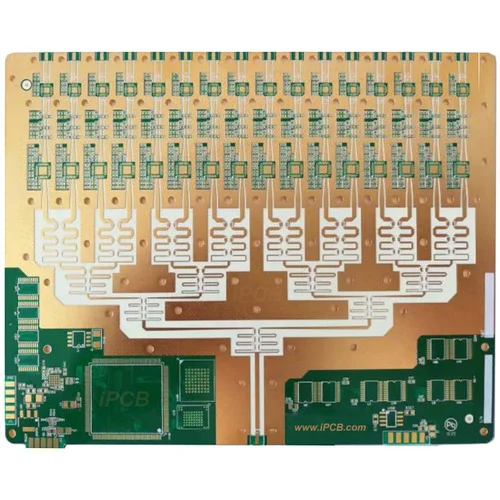
Radar Applications Using Duroid 5880 PCBs
Duroid 5880 radar PCBs are widely applied in:
-
Automotive radar sensors (77GHz / 79GHz)
-
Industrial imaging and sensing radar
-
Aerospace and defense radar modules
-
Precision measurement and detection systems
These applications demand ultra-low loss and long-term stability.
Selecting a Manufacturer for Duroid 5880 PCB for Radar Module
When choosing a supplier, critical factors include:
-
Proven experience with PTFE and Duroid materials
-
mmWave PCB fabrication expertise
-
Controlled impedance manufacturing and testing
-
Capability to scale from prototype to volume production
A qualified partner ensures consistent radar performance across all production stages.
Conclusion
Duroid 5880 PCB for radar module designs play a vital role in achieving low-loss transmission, phase accuracy, and reliable mmWave performance. By combining the right material choice with precise manufacturing control, radar systems can achieve superior detection accuracy and operational stability.
For high-precision radar applications, Duroid 5880 remains a benchmark material that supports both current and next-generation radar technologies.
