CLTE-AT™ laminates are high-performance Rogers high-frequency PCB materials designed for applications that require exceptional dimensional stability, low dielectric loss, and ultra-reliable performance under thermal stress. These laminates are widely used in RF PCB design, microwave circuits, phased array antennas, radar systems, and high-reliability communication systems.
As a member of the CLTE series, CLTE-AT is engineered to deliver a balanced combination of electrical performance, mechanical stability, and thermal reliability, making it suitable for advanced multilayer PCB structures.
Material Overview (CLTE-AT)
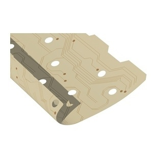
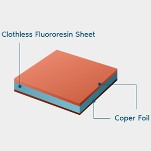
CLTE-AT is a ceramic-filled PTFE-based composite laminate reinforced with woven glass. It is specifically designed to maintain stable electrical properties across temperature variations and mechanical stress conditions.
This makes it ideal for:
- High-frequency RF circuits
- High-layer-count multilayer PCB designs
- Systems requiring tight impedance control
- Long-term reliability in harsh environments
Key Electrical Properties
CLTE-AT provides excellent RF performance due to its stable dielectric characteristics:
Dielectric Constant (Dk)
εr≈3.00\varepsilon_r \approx 3.00εr≈3.00
- Typical dielectric constant: 3.00 ± 0.04 @ 10 GHz
- Extremely stable over temperature and frequency
- Ensures consistent controlled impedance PCB design
Dissipation Factor (Df)
tanδ≈0.0013\tan\delta \approx 0.0013tanδ≈0.0013
- Very low loss tangent
- Excellent for low insertion loss RF PCB applications
- Supports high-frequency signal integrity
Thermal and Mechanical Properties
CLTE-AT is optimized for thermal reliability and dimensional stability, which is critical in multilayer RF PCB fabrication.
Coefficient of Thermal Expansion (CTE)
- X-axis: ~8 ppm/°C
- Y-axis: ~8 ppm/°C
- Z-axis: ~20 ppm/°C
These ultra-low CTE values significantly improve:
- Via reliability in multilayer PCBs
- Thermal cycling durability
- Mechanical stability during PCB assembly
Thermal Conductivity
- Approximately 0.64 W/m·K
This helps:
- Improve heat dissipation in RF power circuits
- Reduce localized hot spots in high-power PCB designs
Electrical Stability Advantages
One of the most important features of CLTE-AT is its stable dielectric performance across temperature ranges:
- Minimal dielectric constant variation with temperature
- Stable phase performance in RF transmission lines
- Reduced signal distortion in microwave frequencies
This is essential for:
- Phased array antennas
- 5G/6G communication modules
- Radar and satellite systems
Mechanical and Reliability Benefits
CLTE-AT laminates are engineered for high-reliability PCB manufacturing environments:
- Excellent plated through-hole reliability (PTH)
- Reduced mechanical stress on solder joints
- Strong adhesion with copper foils
- Suitable for heavy copper and multilayer stack-ups
These properties make it highly suitable for:
- Aerospace electronics
- Defense RF systems
- High-reliability industrial communication boards
Key Advantages of CLTE-AT Laminates
- Ultra-stable dielectric constant (~3.0)
- Very low loss tangent (~0.0013)
- Excellent dimensional stability (low CTE)
- High multilayer PCB reliability
- Low signal distortion at microwave frequencies
- Strong compatibility with complex RF PCB designs
Typical Applications
CLTE-AT laminates are widely used in:
- RF and microwave PCBs
- Phased array antenna systems
- Radar and defense electronics
- Power amplifiers
- Communication base stations
- High-speed RF modules
- Aerospace and satellite systems
Conclusion
The CLTE-AT laminate data sheet highlights a high-performance RF PCB material engineered for low loss, high stability, and superior dimensional control. With its combination of stable dielectric properties, low CTE, and excellent thermal behavior, CLTE-AT is an ideal choice for next-generation high-frequency and high-reliability PCB applications.
For engineers designing advanced RF systems, CLTE-AT provides a strong foundation for achieving consistent impedance control, minimal signal loss, and long-term system reliability.
