
RO4350B Starting Point Compensation Factors: This study was conducted to evaluate dimensional movement of Rogers RO4350B Product through the circuit…
This study was conducted to evaluate dimensional movement of Rogers RO4350B Product through the circuit fabrication process. The study was conducted using Six Sigma tools and the DMAIC process as a guideline for the evaluation (Define, Measure, Analyze, Improve, and Control). The Six Sigma project was initiated as a joint exercise between Rogers Corporation and printed circuit board manufacturer Cirtech Inc.
Notes:
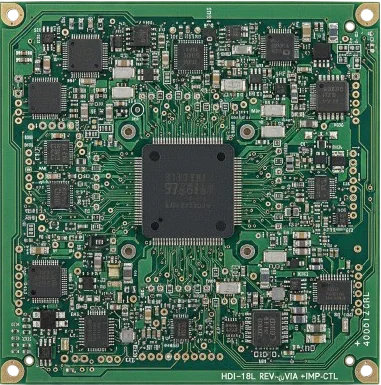
The following information was generated using a uniformly distributed dot matrix image encompassing the critical parameters illustrated in the matrix below. Rogers RO4450B standard lamination cycle was used as outlined in Rogers’ “RO4400 Series Prepreg Data Sheet and Processing Guidelines”. The machine and cross machine directions (MD, CMD) are based on an 18” X 24” panel size. MD is the 18” dimension and CMD is the 24” dimension.
Critical Parameters
| Product Grade |
Dielectric Thickness |
Copper Weight |
% Cu. Etch |
% Cu. Etch |
% Cu. Etch |
Post Process |
Post Process |
|||||||||||||||
| RO4350 | 0.0066 0.010 0.020 |
1 oz. 1 oz. 1 oz. |
25% 25% 25% |
50% 50% 50% |
75% 75% 75% |
X X X |
X X X |
|||||||||||||||
| RO4350 | 0.0066 0.010 0.020 |
0.5oz 0.5oz 0.5oz |
25% 25% 25% |
50% 50% 50% |
75% 75% 75% |
X X X |
X X X |
|||||||||||||||
Materials were measured for dimensional change in both the post etch and post lamination conditions. Results of this analysis indicate that generally 80% of the movement generated from these two processes is experienced during the lamination cycle.



| 0.0066” Thx. | Post MD |
Etch CMD |
Mils/in. X-bar |
Post MD |
Lamination CMD |
Mils/in. X-bar |
|||||||||||||||||
| 0.5oz 25% | -0.0075000 | -0.1000000 | -0.0537500 | -0.2000000 | -0.4900000 | -0.3450000 | |||||||||||||||||
| 0.5oz 50% | -0.0125000 | -0.0800000 | -0.0462500 | -0.2200000 | -0.4400000 | -0.3300000 | |||||||||||||||||
| 0.5oz 75% | -0.0425000 | -0.0025000 | -0.0225000 | -0.1900000 | -0.4150000 | -0.3025000 | |||||||||||||||||
| 0.010” Thx | MD | CMD | X-bar | MD | CMD | X-bar | |||||||||||||||||
| 0.5oz 25% | -0.0230000 | -0.1050000 | -0.0640000 | -0.2800000 | -0.4400000 | -0.3600000 | |||||||||||||||||
| 0.5oz 50% | -0.0280000 | -0.0310000 | -0.0295000 | -0.2450000 | -0.4350000 | -0.3400000 | |||||||||||||||||
| 0.5oz 75% | -0.0100000 | -0.0350000 | -0.0225000 | -0.2250000 | -0.3700000 | -0.2975000 | |||||||||||||||||
| 0.020” Thx | MD | CMD | X-bar | MD | CMD | X-bar | |||||||||||||||||
| 0.5oz 25% | -0.0450000 | -0.0875000 | -0.0662500 | -0.3500000 | -0.3650000 | -0.3575000 | |||||||||||||||||
| 0.5oz 50% | -0.0425000 | -0.0375000 | -0.0400000 | -0.3100000 | -0.3000000 | -0.3050000 | |||||||||||||||||
| 0.5oz 75% | -0.0225000 | -0.0325000 | -0.0275000 | -0.2750000 | -0.2600000 | -0.2675000 | |||||||||||||||||
| Post | Etch | Mils/in. | Post | Lamination | Mils/in. | ||||||||||||||||||
| 0.0066” Thx | MD | CMD | X-bar | MD | CMD | X-bar | |||||||||||||||||
| 1oz 25% | -0.1175000 | -0.2400000 | -0.1787500 | -0.4100000 | -0.6100000 | -0.5100000 | |||||||||||||||||
| 1oz 50% | 0.0000000 | -0.1175000 | -0.0587500 | -0.2450000 | -0.5400000 | -0.3925000 | |||||||||||||||||
| 1oz 75% | 0.0700000 | -0.0350000 | 0.0175000 | -0.1150000 | -0.3450000 | -0.2300000 | |||||||||||||||||
| 0.010” Thx
1oz 25% |
MD
-0.1075000 |
CMD
-0.1500000 |
X-bar
-0.1287500 |
MD
-0.3350000 |
CMD
-0.6450000 |
X-bar
-0.4900000 |
|||||||||||||||||
| 0.020” Thx
1oz 25% |
MD
-0.1175000 |
CMD
-0.0400000 |
X-bar
-0.0787500 |
MD
-0.2750000 |
CMD
-0.3500000 |
X-bar
-0.3125000 |
|||||||||||||||||
For questions or comments please do not hesitate to contact your Rogers Corporation representative.
Applying RO4350B Compensation Factors at KKPCB
Compensation factors are a starting point; each factory still needs to confirm them on its own process. At KKPCB, RO4350B panels are measured after key steps, and artwork scaling is adjusted when the measured movement differs from the expected value. Panels are baked before lamination to remove moisture, which also improves dimensional repeatability.
For multilayer RO4350B builds, registration between layers is verified before drilling, and impedance coupons confirm the final result. Send your RO4350B stack-up for review, and see our high-frequency PCB capabilities.