
Aerospace PCB revision control for long-life programs begins before a substitute part reaches production. Risk appears when a component reaches end of life, procurement proposes an alternate, and the electrical design, land pattern, fabrication files, assembly instructions, and verification baseline no longer describe the same hardware. A Aerospace PCB release therefore needs a controlled change path that keeps product intent visible to engineering, purchasing, manufacturing, and quality.
For a long-life Aerospace PCB program, the challenge is keeping a representative airborne controller or mission instrument build coherent across multiple procurement cycles. It is an engineering workflow, not a KKPCB customer case or qualification claim. NASA parts-assurance and configuration-management material offers useful high-reliability practice, but space-flight rules apply only when the governing contract or program invokes them; aeronautics projects must follow their own authority. For board-level feasibility, align the Aerospace PCB requirements with the program’s actual environment and acceptance basis.

Why Aerospace PCB Revision Control Starts With an EEE Part Change
An Aerospace PCB alternate is not automatically interchangeable. Package outline, terminal assignment, exposed-pad geometry, pin-1 orientation, recommended land pattern, input capacitance, switching behavior, thermal resistance, voltage margin, and manufacturing restrictions may differ. Even when the footprint appears identical, a substitute can change loop area, decoupling placement, return-current geometry, noise coupling, thermal flow, or firmware configuration. The correct question is not whether two catalog entries look similar; it is whether the proposed device preserves every requirement allocated to the affected circuit and assembly.
Start with the approved PCB design baseline: schematic revision, library symbol and footprint revision, netlist, stackup, placement constraints, copper and drill data, assembly drawing, BOM, test limits, and software or programmable-device dependencies. Map each changed item to affected nets, neighboring components, power rails, connector interfaces, thermal paths, and inspection points. A footprint-only edit on an Aerospace PCB can still invalidate a thermal pad stencil or change access for rework.
| Change trigger | Board-level review | Release evidence |
|---|---|---|
| Part marked not recommended for new design or end-of-life | Remaining demand, approved inventory, sourcing risk, and redesign lead time | Lifecycle notice, affected assemblies, and disposition owner |
| Alternate with a different package or pin map | Land pattern, clearance, routing, polarity, thermal and assembly fit | Updated library, drawing, netlist, and engineering approval |
| Electrical alternate in the same package | Operating limits, stability, transient response, noise, startup and fault behavior | Analysis rationale and project-defined verification results |
| Fabrication or assembly process change | Stackup, finishes, solder process, inspection and product-level impact | Revised supplier package and acceptance plan |
Qualify an alternate against the application, not the distributor description
Record the original manufacturer part number and revision, proposed replacement, lifecycle status, source, lot traceability needs, and the exact reason for the change. Then compare datasheet limits and package drawings at the project’s worst-case conditions: supply range, temperature, load, startup state, fault state, and expected duty cycle. For an analog front end, check input range, offset, noise, bias current, and stability with the actual source impedance. For a regulator, review control-loop requirements, output-capacitor range, switching frequency, transient response, and heat flow. For a digital device, include timing, boot configuration, reset behavior, firmware drivers, and any security or export constraints.
Use a documented EEE component sourcing process to distinguish supplier availability from engineering approval. An internal approved-parts list is not a substitute for project acceptance. NASA’s Parts Selection List is an aid for NASA flight projects and its presence does not grant approval for another program. Likewise, do not infer radiation tolerance, screening level, or service life from a family name. If the program requires screening or derating, identify the controlling document, authority, and records before procurement.
Ask the design owner to classify the change: direct replacement, constrained alternate, or redesign. A direct replacement still needs an equivalence rationale; a constrained alternate may require assembly-specific instructions; a redesign affects the electrical and mechanical baseline. Capture this decision in the change-impact review with named approvers and open actions. Do not let a buyer’s substitution silently update the production BOM.
Keep the fabrication and assembly package on one revision baseline
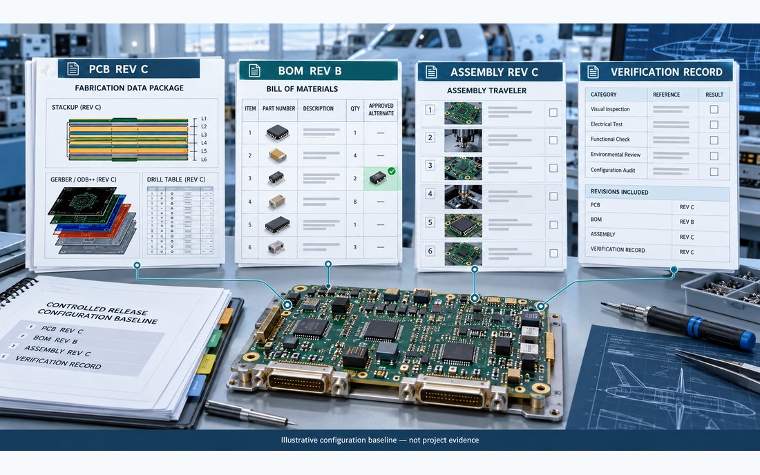
The PCB data package should be internally consistent and traceable. Identify the released fabrication data set, stackup and layer planning, material callouts and controlled-impedance notes if applicable, drill and route files, copper balance, surface finish, solder-mask openings, panelization, and revision-specific readme. If the alternate changes pin usage or component placement, update the schematic, netlist, artwork, pick-and-place data, stencil apertures, assembly drawing, polarity marks, inspection criteria, and test fixture documentation as appropriate. A version label on the title block alone does not prove that all files belong together.
For a controlled PCB production capability check, compare the changed design with the actual stackup and process notes rather than assuming a previous build remains representative. Where a short pilot is useful, a production-intent prototype build should use the proposed part, released library, stencil, and assembly instructions. If a surface-mount package changes, review the SMT assembly process for paste coverage, component seating, reflow compatibility, inspection access, and rework limitations. Also complete a PCB assembly capability review against the actual package and inspection needs. Through-hole connectors or power devices may need a separate review of through-hole assembly details.
Configuration management is not paperwork added after design. NASA describes it as maintaining visibility and control over functional and physical characteristics through the product life cycle. In practice, a change record should identify the “as-designed,” “as-built,” and “as-tested” states, including effective serial or lot range, approved deviations, supplier acknowledgment, and the point at which old data is no longer valid. Apply quality-control records to make the evidence retrievable, not merely to accumulate forms.
Plan verification around what changed
For an Aerospace PCB program, verification should close the risk created by the change. A footprint or pin-map change may require continuity, polarity, isolation, and functional checks; a power component may require startup, load-step, thermal, and fault-response evidence; a change near a sensitive RF or clock path may require the project’s defined signal-integrity or receiver-performance checks. A new solderable finish, package, or reflow profile can call for workmanship and assembly acceptance review. These are candidate methods, not blanket test mandates: acceptance limits, sample size, and environmental conditions must come from the program’s approved plan.
Do not claim that analysis alone proves flight suitability, and do not treat one successful prototype as statistical qualification. For higher-risk changes, define a review matrix that links each affected requirement to an analysis, inspection, or test, plus the responsible approver. The Aerospace PCB delivery record should make it possible to identify exactly which design data, component lots, assembly instructions, and verification records apply to each delivered configuration.
A practical release decision for the program manager
Three responses are common when a critical component becomes unavailable: secure a justified lifetime quantity, approve a qualified alternate for a bounded build range, or redesign the circuit and board. A lifetime buy trades immediate redesign effort for storage, shelf-life, traceability, and forecast risk; an alternate trades schedule for technical equivalence and change-control effort; a redesign offers a cleaner long-term baseline but may affect qualification and tooling. There is no universal best option. Compare demand confidence, remaining supplier support, environmental exposure, redesign scope, verification effort, and the cost of holding an obsolete configuration.
- Identify the exact affected assembly, serial range, and current approved data set.
- Confirm whether the change is source-only, electrical, mechanical, process-related, or a combination.
- Compare the alternate’s package and limits against the circuit’s actual operating corners.
- Review library, copper, stencil, panel, assembly, inspection, test, and firmware impacts.
- Set approval authority and required evidence before purchasing or building the alternate.
- Release a coordinated revision package and archive superseded data with clear status.
- Confirm supplier receipt of the same baseline and disposition any existing inventory.
For Aerospace PCB production, a disciplined change record prevents procurement convenience from becoming an undocumented design change. Engineering owns technical acceptability; the program’s quality and customer authorities own acceptance; manufacturing needs a clear, reproducible data set. This separation supports long-life service without implying a qualification result or customer project that has not been documented.
Sources: NASA-STD-8739.10, EEE Parts Management and Control Requirements for Space Flight Hardware (scope applies to space-flight hardware when invoked, not automatically to aeronautics); NASA Parts Selection List and its use notes; NASA Systems Engineering Handbook, Configuration Management; MSFC-STD-3620, EEE Parts Obsolescence Management and Control Requirements (MSFC-specific). These references inform the workflow; each aviation program must apply its own contract, authority, revision baseline, and acceptance criteria.





