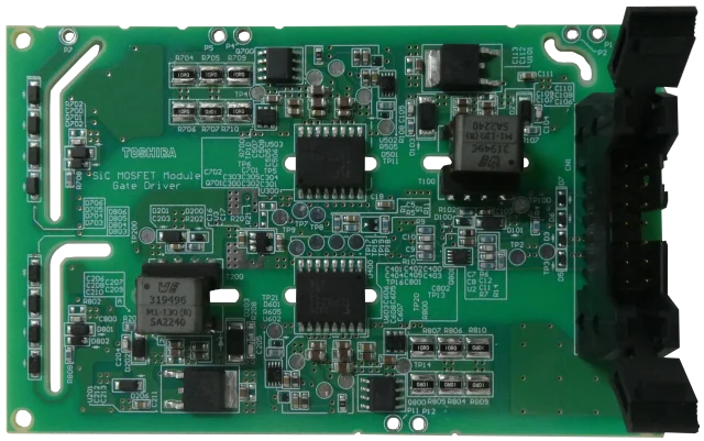
What Is a SiC PCB?
A SiC PCB is a printed circuit board specifically designed to support Silicon Carbide (SiC) power devices. SiC semiconductors operate at higher voltages, higher temperatures, and higher switching frequencies compared to traditional silicon devices.
Because of these characteristics, the PCB supporting SiC components must provide superior thermal management, electrical insulation, and structural reliability.
Why SiC Devices Require Specialized PCB Design
Silicon Carbide power modules are widely used in:
-
Electric vehicles (EV)
-
Solar inverters
-
Industrial motor drives
-
High-voltage power conversion systems
Compared to conventional silicon MOSFETs or IGBTs, SiC devices:
-
Switch faster
-
Operate at higher junction temperatures
-
Generate concentrated heat
-
Require lower parasitic inductance
Standard PCB designs may not meet these demanding requirements.
Key Design Requirements for SiC PCB
1. High Thermal Conductivity
SiC devices can operate at junction temperatures above 175°C. Efficient heat dissipation is essential.
Common thermal solutions include:
-
Thick copper layers
-
Thermal vias
-
Metal core structures
-
Ceramic substrates (such as aluminum nitride)
Effective heat spreading improves device lifetime and performance stability.
2. High Voltage Insulation
SiC power systems often operate at:
-
600V
-
800V
-
1200V or higher
PCB design must ensure:
-
Adequate creepage and clearance distances
-
High CTI materials
-
Strong dielectric strength
-
Controlled layer spacing
Electrical insulation reliability is critical for safety compliance.
3. Low Parasitic Inductance Layout
High switching speeds increase sensitivity to parasitic inductance.
Design strategies include:
-
Short and wide current paths
-
Optimized loop area
-
Laminated busbar-style routing
-
Multilayer plane coupling
Reduced parasitics improve switching efficiency and reduce EMI.
4. High TG and Thermal Stability
SiC systems generate repeated thermal cycling stress. High TG materials provide:
-
Improved mechanical stability
-
Reduced warpage
-
Better via reliability
-
Resistance to delamination
This is especially important in automotive and industrial applications.
Common SiC PCB Structures
Depending on application requirements, SiC PCBs may use:
-
Thick copper multilayer boards
-
Insulated metal substrate (IMS)
-
Ceramic-based substrates
-
Hybrid stack-ups combining FR4 and high-performance materials
Material selection depends on voltage, power density, and thermal performance targets.
Applications of SiC PCB
SiC PCB solutions are widely used in:
-
EV onboard chargers
-
DC-DC converters
-
Traction inverters
-
Solar power inverters
-
Industrial automation systems
-
Energy storage systems
As electrification accelerates, SiC-compatible PCB design becomes increasingly important.
SiC PCB vs Standard Power PCB
| Feature | Standard Power PCB | SiC PCB |
|---|---|---|
| Switching Speed | Moderate | Very High |
| Operating Temperature | Lower | Higher |
| Voltage Level | Moderate | High |
| Thermal Requirement | High | Very High |
| Parasitic Control | Important | Critical |
SiC PCBs are optimized for higher performance and stricter reliability standards.
Conclusion
SiC PCB technology supports the next generation of high-efficiency, high-voltage power systems. Through advanced thermal management, robust insulation design, and low-inductance routing, SiC-compatible PCBs ensure safe, reliable, and high-performance operation.
As electric vehicles and renewable energy systems continue to expand, SiC PCB design will remain a key enabler of efficient power conversion technology.
