Radar modules operating at microwave and millimeter-wave frequencies demand exceptional signal integrity, minimal transmission loss, and long-term stability. Duroid 5880 PCB for radar module applications is widely recognized as one of the most reliable solutions for high-frequency radar systems used in automotive, aerospace, and industrial sensing.
Its unique material properties make Duroid 5880 especially suitable for precision radar signal transmission.
What Is Duroid 5880 PCB?
Duroid 5880 PCB is based on Rogers RT/duroid® 5880 laminate, a PTFE composite reinforced with glass microfibers. It is engineered specifically for microwave and mmWave circuits requiring ultra-low dielectric loss.
Key characteristics include:
-
Dielectric constant (Dk) ≈ 2.2
-
Extremely low dissipation factor (Df ≈ 0.0009 @ 10 GHz)
-
Excellent phase stability across temperature changes
-
Very low moisture absorption
These features make Duroid 5880 PCB for radar module designs ideal for high-frequency environments.
Why Duroid 5880 Is Ideal for Radar Modules
Ultra-Low Dielectric Loss
Radar performance depends on clean signal transmission. Duroid 5880 minimizes insertion loss, enabling longer detection range and higher resolution.
Stable Electrical Performance
A consistent dielectric constant ensures accurate impedance control, which is critical for radar RF paths and antenna structures.
Superior mmWave Capability
Duroid 5880 PCB performs reliably at 24 GHz, 77 GHz, and 79 GHz, making it suitable for modern automotive and industrial radar modules.
Controlled Impedance for Duroid 5880 Radar PCBs
A professional Duroid 5880 PCB for radar module requires precise impedance control:
-
Stackup simulation and impedance calculation
-
Tight control of dielectric thickness and copper geometry
-
Controlled impedance fabrication (±5% or tighter)
-
TDR impedance measurement and verification
Accurate impedance control reduces signal reflection and phase distortion.
Duroid 5880 PCB Stackup Options for Radar Modules
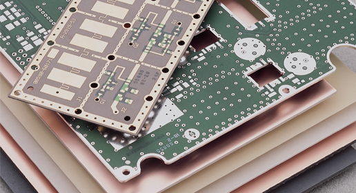
Common stackup configurations include:
-
Single-layer or double-layer radar antenna boards
-
Multilayer radar PCBs with dedicated ground planes
-
Hybrid stackups combining Duroid 5880 with Rogers or high-Tg FR-4
Hybrid designs help balance RF performance, mechanical strength, and cost.
Manufacturing Challenges of Duroid 5880 PCBs
Producing Duroid 5880 PCB for radar module applications requires advanced RF manufacturing expertise:
-
Specialized drilling and via plating for PTFE materials
-
Copper roughness control to reduce conductor loss
-
Fine-line etching for mmWave RF traces
-
Stable lamination and registration for multilayer boards
Experienced manufacturers implement strict process control to ensure consistency.
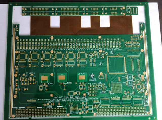
Applications of Duroid 5880 PCB for Radar Modules
Duroid 5880 radar PCBs are widely used in:
-
Automotive radar systems (ACC, AEB, BSD)
-
Industrial sensing and imaging radar
-
Aerospace and defense radar platforms
-
High-frequency RF and mmWave front-end modules
These applications demand ultra-low loss and high reliability.
Choosing a Manufacturer for Duroid 5880 PCB for Radar Module
When selecting a supplier, consider:
-
Experience with PTFE and Duroid materials
-
Proven mmWave and radar PCB manufacturing capability
-
Controlled impedance fabrication and testing
-
Prototype-to-mass-production scalability
A qualified partner ensures stable radar performance and consistent production quality.
Conclusion
Duroid 5880 PCB for radar module applications delivers ultra-low dielectric loss, excellent mmWave performance, and stable impedance control for high-precision radar systems. With proper stackup design and RF-focused manufacturing processes, Duroid 5880 PCBs enable accurate detection, reliable operation, and long-term system stability.
Partnering with an experienced Duroid 5880 PCB manufacturer ensures your radar modules meet the highest standards of performance, reliability, and scalability.
