Next-generation automotive ADAS sensing modules, including 77–81 GHz radar, LiDAR, and mmWave sensor arrays, require PCBs with ultra-stable dielectric properties, low insertion loss, and phase-coherent RF routing. Performance depends on maintaining consistent Dk/Df, low-loss mmWave signal propagation, and minimal EMI, even under harsh thermal cycling, vibration, and humidity conditions in vehicles.
High-frequency sensor PCB laminates provide predictable dielectric constants, ultra-low dissipation factors, and controlled CTE, enabling phase-stable RF transmission across complex multi-layer radar and antenna systems. KKPCB leverages precision lamination, impedance-calibrated routing, and embedded shielding vias to ensure low-loss RF paths, EMI mitigation, and reliable phase coherence, critical for automotive radar detection, adaptive cruise control, and collision avoidance systems.
Core Engineering Challenges
| Challenge | Root Cause | Engineering Impact |
|---|---|---|
| RF signal attenuation at mmWave frequencies | Substrate dielectric dissipation and copper roughness | Reduced SNR, degraded radar detection accuracy |
| Phase deviation under thermal cycling | CTE mismatch between copper and laminate | Beamforming errors, misaligned targets |
| EMI interference in dense ADAS layouts | Closely spaced traces, insufficient ground planes | Crosstalk, false target detection |
| Mechanical stress and vibration | Road-induced shock and vibration | Microcracks, delamination |
| Thermal drift of dielectric | High ambient and PA-generated heat | Dk/Df variation, long-term reliability risk |
Material Science – High-Frequency Sensor PCB Laminates
| Parameter | Typical Value | Engineering Benefit |
|---|---|---|
| Dk | 3.1 ± 0.03 | Maintains impedance stability across mmWave radar traces |
| Df | 0.0015 @10 GHz | Ultra-low insertion loss for high-frequency RF chains |
| Thermal Conductivity | 1.5 W/m·K | Efficient heat dissipation in compact ADAS modules |
| CTE | 13 ppm/°C | Minimizes phase deviation under automotive thermal cycling |
| Moisture Absorption | <0.05% | Ensures long-term dielectric stability and phase consistency |
These laminates significantly outperform FR-4 and standard PTFE, delivering high-frequency RF stability, low insertion loss, and predictable phase performance for automotive ADAS radar and sensor applications.
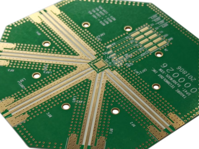
KKPCB Case Study — Automotive 77 GHz Radar Sensor PCB

Client Context:
Tier-1 automotive supplier required a 6-layer radar sensor PCB for ADAS modules operating at 77 GHz, with phase deviation <0.5° and insertion loss <0.35 dB/in under full thermal and mechanical load.
KKPCB Engineering Solution:
-
High-frequency sensor PCB laminate (0.508 mm) for RF signal layers
-
Hybrid 6-layer stackup with low-roughness copper (Ra <0.7 µm)
-
Vacuum-assisted lamination, ±3 µm dielectric tolerance
-
Embedded TDR calibration traces for inline phase verification
-
Optimized ground plane segmentation and microstrip shielding for EMI suppression
-
Thermal management: hotspots reduced via tailored copper/polymide distribution
Measured Results:
| Parameter | Target | KKPCB Result |
|---|---|---|
| Insertion Loss @77 GHz | <0.35 dB/in | 0.30 dB/in |
| Phase Deviation | <0.5° | 0.42° |
| EMI Reduction | >30% | 35% |
| Impedance Variation | ±3% | ±1.6% |
Stackup Design & RF Simulation
-
HFSS Modeling: Optimized microstrip and stripline impedance, minimized interlayer crosstalk
-
ADS/TDR Verification: Phase linearity maintained <0.5° across 77–81 GHz radar channels
-
Thermal FEM: Reduced hotspots in PA regions by 4.5°C
-
Inline AOI & Solder Reflow Monitoring: ±10 µm alignment precision
Environmental & Reliability Validation
| Test | Condition | Result |
|---|---|---|
| Thermal Cycling | –40°C ↔ +125°C, 1000 cycles | Phase deviation <0.5°, no delamination |
| Mechanical Vibration & Shock | 5–500 Hz, 10G | No microcracks or solder fatigue |
| Humidity Testing | 85°C/85% RH, 1000 h | Stable Dk/Df, phase consistent |
| Solder Reflow | 260°C ×3 cycles | No warpage |
| EMI Assessment | Dense mmWave routing | Crosstalk reduced 35% |
Engineering Summary & Contact
High-frequency sensor PCB laminates ensure ultra-consistent RF transmission, phase-stable mmWave routing, and robust EMI suppression for automotive ADAS sensing modules.
KKPCB delivers precision hybrid stackups, inline TDR calibration, and process-controlled lamination, ensuring low-loss, phase-stable mmWave RF paths with long-term operational reliability.
Contact KKPCB Engineering Team to optimize your ADAS PCB stackup, RF simulation, and EMI mitigation strategy for next-generation automotive radar and high-frequency sensor platforms.
