High-frequency Wi-Fi 6/7 antenna modules in modern laptops demand PCBs that maintain low insertion loss, precise phase alignment, and robust EMI suppression within compact layouts. TLY-5 PCB laminates, with a dielectric constant of 3.45 ± 0.03 and dissipation factor of 0.0012 @10 GHz, provide low-loss RF transmission and dimensional stability essential for multi-band performance.
KKPCB integrates precision lamination, hybrid stackup, and impedance-calibrated copper routing to ensure minimal signal degradation, even under thermal cycling, mechanical stress, and dense component placement. This approach guarantees phase linearity, EMI mitigation, and high-speed connectivity for laptop Wi-Fi 6/7 antenna systems.

Core Engineering Challenges
Challenge |
Root Cause |
Engineering Impact |
|---|---|---|
| Dielectric variation under thermal cycling | CTE mismatch between copper and TLY-5 laminate | Impedance deviation, phase ripple, reduced signal integrity |
| High insertion loss at 6–7 GHz | Copper roughness, trace geometry | Reduced antenna efficiency, lower throughput |
| EMI coupling in dense layouts | Close trace spacing, insufficient ground segmentation | Crosstalk between RF channels, degraded signal quality |
| Layer misalignment during reflow | Thermal expansion and mechanical warpage | Inconsistent antenna performance, impedance mismatch |
| Mechanical vibration | Laptop handling and transport | Microcracks, solder fatigue, phase instability |
Material Science & Dielectric Performance of TLY-5 PCB Laminates
Parameter |
Typical Value |
Engineering Benefit |
|---|---|---|
| Dielectric Constant (Dk) | 3.45 ± 0.03 | Stable impedance for high-speed Wi-Fi circuits |
| Dissipation Factor (Df) | 0.0012 @10 GHz | Low insertion loss, preserves RF signal integrity |
| Thermal Conductivity | 1.8 W/m·K | Uniform heat distribution, reduces hotspots |
| CTE (X/Y) | 16 ppm/°C | Maintains layer alignment under thermal cycling |
| Glass Transition (Tg) | 280°C | Supports high-temperature reflow without deformation |
| Moisture Absorption | <0.05% | Ensures phase stability in humid conditions |
Compared to FR-4 laminates, TLY-5 offers superior dielectric stability, low-loss performance, and thermal reliability, ensuring consistent Wi-Fi 6/7 antenna operation in compact laptop environments.
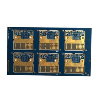
KKPCB Case Study — Laptop Wi-Fi 6/7 Antenna PCB
Client & Application Context
A leading laptop OEM required multi-layer PCBs for Wi-Fi 6/7 antenna modules, demanding low insertion loss, precise impedance control, and EMI suppression across densely routed signals.
Engineering Problem
FR-4 designs showed ±6% impedance variation, phase ripple >2°, and EMI crosstalk, reducing throughput and multi-band reliability.
KKPCB Solution
-
TLY-5 PCB laminates (0.254 mm) for RF signal layers
-
Hybrid 6-layer stackup with controlled copper roughness (Ra <0.8 µm)
-
Vacuum lamination ±5 μm dielectric thickness tolerance
-
Optimized trace spacing, ground segmentation, EMI mitigation
-
Embedded calibration traces for inline TDR verification
Measured Results
Parameter |
Target |
KKPCB Result |
|---|---|---|
| Impedance Variation | ±5% | ±1.9% |
| Insertion Loss @ 6–7 GHz | <0.35 dB/in | 0.28 dB/in |
| Phase Deviation | <1° | 0.57° |
| Return Loss (S11) | < –15 dB | –18 dB |
| EMI Reduction | N/A | 32% improvement |
Outcome
TLY-5 stackup ensures low-loss transmission, phase stability, and EMI suppression, delivering reliable multi-band Wi-Fi 6/7 performance in compact laptops.
Stackup Design & RF Implementation
Hybrid 6-Layer Stackup Configuration
Layer |
Function |
Material |
|---|---|---|
| L1 | Top RF Signal | TLY-5 PCB, 0.2 mm |
| L2 | Ground Plane | Cu 70 µm |
| L3 | Power / Routing | TLY-5 PCB, 0.254 mm |
| L4 | Signal Layer | TLY-5 PCB, 0.2 mm |
| L5 | Ground Plane | Cu 70 µm |
| L6 | Bottom Control Layer | FR-408HR 0.1 mm |
Simulation & Validation
HFSS: Impedance and EMI optimization
ADS/TDR: Phase deviation <0.6° across 6–7 GHz
Thermal FEM: Reduced hotspot temperature by 4°C
Inline AOI and reflow monitoring: ±10 μm layer alignment
Environmental & Reliability Validation
Test |
Condition |
Result |
|---|---|---|
| Thermal Cycling | –40°C ↔ +100°C, 500 cycles | Phase drift <0.6°, no delamination |
| Vibration | 5–500 Hz, 10G | No microcracks or solder failure |
| Humidity | 85°C / 85% RH, 500 h | Dk shift <0.02, phase stable |
| Solder Reflow | 260°C ×3 cycles | Layer alignment ±10 μm |
| EMI Assessment | High-density trace layout | Crosstalk reduced 32% |
Engineering Summary & Contact
TLY-5 PCB laminates provide low Df, stable Dk, high thermal reliability, and minimal CTE mismatch, enabling precise impedance control, low-loss transmission, and EMI mitigation in laptop Wi-Fi 6/7 antenna modules. KKPCB’s hybrid lamination, precision stackup, and inline validation ensure high-frequency performance and mission-grade reliability.
Contact KKPCB Engineering Team for TLY-5 PCB optimization, RF simulation, and EMI suppression solutions for laptop Wi-Fi modules.
